Roduct, Pecifications – OPTI-UPS OD1000 User Manual
Page 4
3.
P
RODUCT
S
PECIFICATIONS
Model Name
OD330 OD330-AL
OD500
OD1000
Capacity
330 VA / 200 W
500VA/300W
1000VA/600W
Voltage
120V/220 Vac ± 30 %
Input
Frequency
50/60 Hz ± 10 %
auto sensing
Voltage
(on battery mode)
Square wave 220 Vac ± 5 %
Frequency
(on battery mode)
50/60 Hz ± 1 Hz
Automatic voltage
adjustment
When the input voltage is 9 % to 15 % lower than the utility, the UPS
automatically boosts the voltage by 15 %
When the input voltage is 9 % to 15 % higher than the utility, the UPS
automatically bucks the voltage by 13 %
Output
Transfer Time
4ms (typical)
Surge protection
250 J
2 m s
Overload protection
When the load is more than 110%, the UPS will automatically
shut down in 60 seconds
When the load is more than 130%, the UPS will automatically
shut down in 3 seconds
EMI
RFI filter
10 db at 0.15 MHz, 50 db at 30 MHz
Short circuit
Immediately cut off the input or output circuit breaker protection
Battery low voltage
Low voltage discharge protection, battery failure warning
Too hot
Automatically turn on the cooling fan
Protection &
Filtering
Higher or lower voltage
Switch to battery mode
Quantity
1 * 12V batter
2 * 12V batteries
parallel connection
2 * 12V batteries
Series connection
Charging current
5A/10A/15A/20A
Battery
Battery protection
Discharge low voltage protection, battery failure warning
Mains electricity normal
Green light is on
Battery mode
Orange light is on
Indicators
Battery / UPS fault
Red light is on
Working environment
-20
60
, highest 3500m, 0
95% (without condensation
Working noise
< 40db
1 meter away from the UPS surface
Environment
Storage
0 to 15000m
Weight
kg
(excluding the battery)
Net weight 16
Gross weight 18
Net weight 23
Gross weight 25
Net weight 25
Gross weight 28
Dimensions W×D×H
including installation
support and handle
535Ч310Ч580
mm
535Ч310Ч870
mm
Physical
Connections
Wirable terminal blocks
6
4.1 Inspection
P l e a s e i n s p e c t U P S i m m e d i a t e l y f o r m i s s i n g p a r t s o r o t h e r p r o b l e m s .
S h o u l d t h e r e b e a n y d a m a g e , p l e a s e n o t i f y t h e s e l l e r.
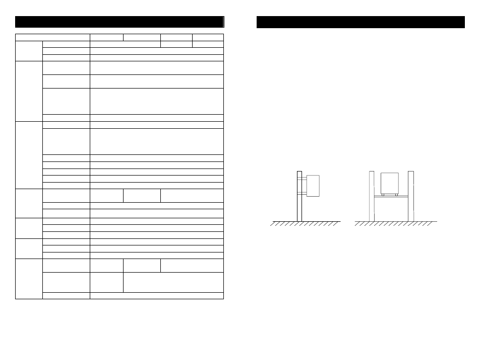
4.2 Installing the UPS Cabinet
z Electric pole installation: Anchor Ear Installation. Behind the UPS
c a b i n e t a r e 2 i n s t a l l a t i o n p o l e s . P l e a s e p i c k t h e s i z e o f t h e i n s t a l l a t i o n
p o l e s t h a t y o u w i l l n e e d .
z H-pole installation: Fastening Screw Installation. Below the UPS
c a b i n e t a r e 2 i n s t a l l a t i o n p o l e s . T h e U P S i s p l a c e d o n t h e H - p o l e , a n d
f o u r f a s t e n i n g s c r e w s a r e u s e d t o f i x t h e U P S c a b i n e t .
z Wall installation: Expanding Screws plus A-Frame Installation. The
e x p a n d i n g s c r e w s a r e f i x e d o n t h e w a l l a c c o r d i n g t o t h e d i s t a n c e o f
f o u r i n s t a l l a t i o n h o l e s . T h e n t h e A - f r a m e w i l l b e i n s t a l l e d a n d
f a s t e n e d o n t h e 2 i n s t a l l a t i o n p o l e s b e l o w t h e U P S c a b i n e t .
7