Mossberg AT User Manual
Page 5
The mechanical safety lever of your Mossberg firearm works directly with the
trigger assembly. For this reason, the trigger mechanism is permanently set at the
factory. Any attempt to change these factory settings may render the safety
inoperative and thus create a hazardous condition that could cause serious injury
or death to you or those around you. The trigger and safety mechanisms have
been designed to function properly in their original condition. Any changes to those
mechanisms are specifically contrary to our instructions and we expressly DO
NOT authorize any changes to be made after original manufacture.
TO INSTALL BOLT IN THE RIFLE
Visually and physically check to make certain there is no ammunition in
the chamber or magazine. Keep the muzzle pointed in a safe direction at
all times.
A. With the bolt handle pointing up and to the right, align the locking lugs on the
bolt with the matching machined cuts in the rear of the receiver.
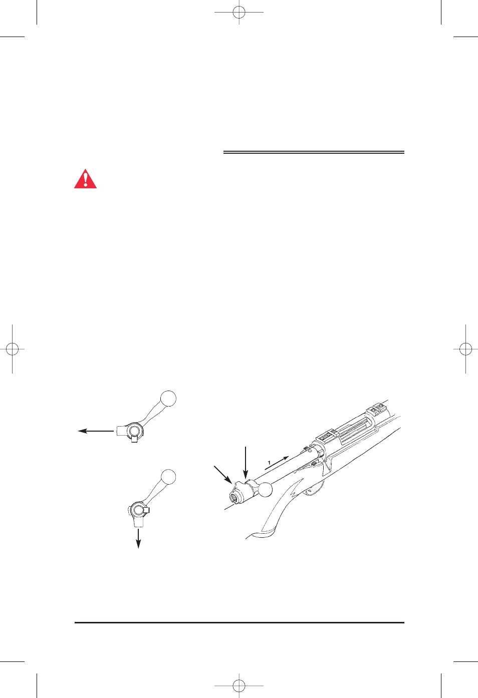
When assembling the bolt into the rifle, make sure the position of the bolt sleeve is as
shown in Fig. A. If it is not, the bolt will not close fully and the tab on the bolt sleeve
will hit the top of the stock and may cause damage to your stock. The bolt handle
assembly is designed so that it cannot be installed in the rifle unless it is in correct
alignment.
The correct bolt assembly orientation is shown in figure A. With the bolt handle up
and to the right, the tab on the bolt sleeve is horizontal and to the left.
The orientation shown in Fig. B requires resetting the bolt sleeve to the position
shown in Fig. A. This may be done by holding the tab on the bolt sleeve in a vise with
padded jaws (to prevent marring of the part) and rotating the bolt handle counter
clockwise until it is the same as Fig. A before assembling the bolt into the gun.
B. Push the bolt forward gently into the receiver about one inch, until the bolt-stop
snaps into place behind the bolt lugs holding the bolt in place.
3
Figure 3
Fig. A
TAB POINTS
LEFT
REQUIRES
RESETTING
CORRECT ORI-
ENTATION
TAB
POINTS
LEFT
TAB POINTS
DOWN
BOLT SLEEVE
Fig. B
65148_Eng 6/27/08 8:25 AM Page 3