Mossberg 590 User Manual
Page 14
12
Trigger housing assemBly insTallaTion
NOTE: Hammer must be in the fully-cocked position to allow the trigger housing to be
inserted in the receiver.
Hold the cartridge stop and cartridge interrupter in place firmly against the receiver walls with
one hand and grasp the trigger housing assembly with the other (Fig. 9).
Insert the lugs on each side of the front corner of the trigger housing into the slots on each side
of the receiver (Fig. 14-A), then ease the rear of the housing assembly down and into position
(Fig. 14-B). DO NOT FORCE!
NOTE: If the trigger housing does not fit into place easily, check that all internal trigger housing
pins are flush with the side of the housing and that the cartridge interrupter and cartridge
stop are positioned properly.
Align the trigger pin hole in the housing assembly with those in the receiver. Insert the trigger
housing pin and push in fully until flush with the side of the receiver (Fig. 14).
Position the cartridge stop and cartridge interrupter in their proper places on the inside walls of
the receiver (Fig. 9).
The hooks must face inward toward the center of the cavity away from the receiver walls.
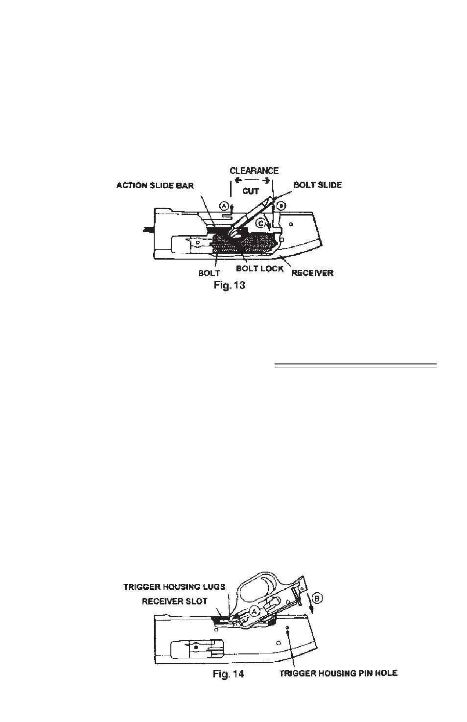
Position action bars so the notch on the bar is even with the cuts on the inside receiver walls
(Fig. 13-A).
The bolt slide should be positioned with the slotted side facing up, with notch to the rear (Fig. 13).
Assemble the bolt slide, lowering the front of the bolt slide first. The bolt slide protrusion fits into
the corresponding cut on the bottom of the bolt lock and action bar slots (Fig. 13-C).
Hold the bolt slide down and pull the forearm assembly forward. The bolt and bolt slide should
move freely in their cuts in the receiver. If parts do not slide easily – DO NOT FORCE –
disassemble and reassemble, paying attention to the relationship of the bolt, bolt slide and
action slide bars.