Preparation of the gate, Installation overview, Step 1 – Mighty Mule FM700 User Manual
Page 15: Step 2, Pull-to-open gates (gate opens into the property)
11
Horizontal Cross Member
Gate Swings Evenly and Freely
Hung Firmly and Plumb
Receiver
Post Bracket Assembly
Control Box with Battery
Gate Bracket
Single Gate Opener
Fence Post Set in Concrete
Run 1000’ (max.) of low
voltage wire to control
box from transformer
(wire not included).
Power Cable
Closed Position Positive Stop Plate
120 Volt indoor
Transformer
(surge protector
not supplied)
PVC conduit (not included)
to protect wire from lawn
mowers and weed eaters.
Warning Sign
Preparation of the Gate
Step 1
The gate must be plumb, level, and swing freely on its
hinges. Wheels must not be attached to the gate. The
gate must move throughout its arc without binding or
dragging on the ground. Note that gates over 250 lb.
should have ball bearing hinges with grease fittings.
Step 2
The fence post must be secured in the ground with
concrete so it will not twist or flex when the opener is
activated. Be sure to position the opener near the
centerline of the gate to keep the gate from twisting and
flexing. The addition of a horizontal or vertical cross
member (if one is not already in place) to provide a
stable area for mounting the gate bracket is also
important.
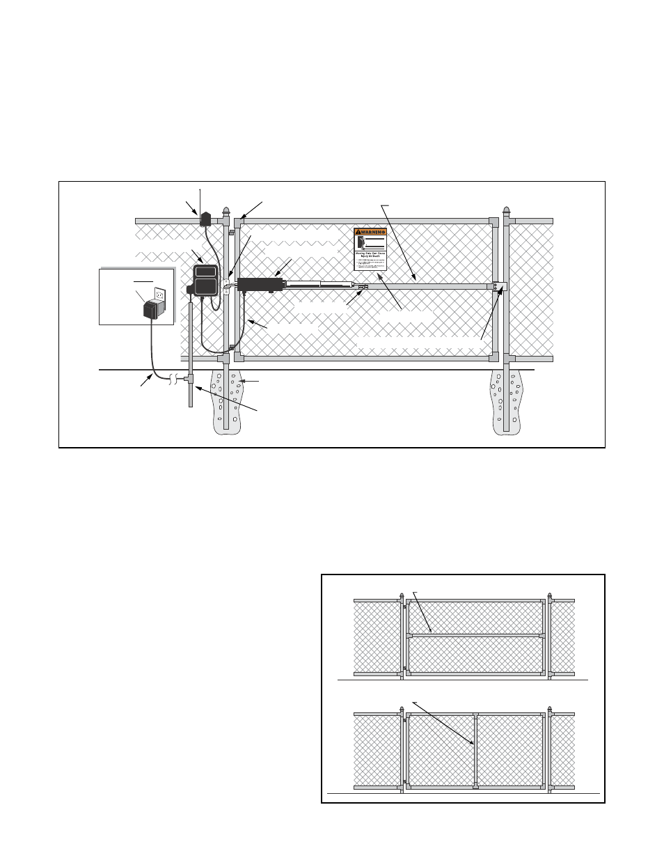
Installation Overview
Pull-to-Open Gates (Gate Opens into the Property)
The diagram shown below is an example of a pull-to-open installation on a chain link fence and single gate. Mounting the
opener on a masonry column requires special procedures; see Column Installation Information on page 34 if you intend to
mount the opener on a column. Furthermore, if you have a push-to-open gate, you will need to purchase a push-to-open kit
(see Accessory Catalog) to properly configure your system. See Push to Open Installation on page 29 before proceeding.
Horizontal Cross Member
Vertical Cross Member