Lingenfelter L460040000 Lingenfelter RPM-002 RPM Activated Switch Instructions v2.3 User Manual
Page 7
To set a new Low RPM, follow instructions to switch back to Normal mode, and then back to Window Mode and set Low
RPM as outlined above.
Normal Mode Power Up – The Red LED will come on steady at power up.
Normal Mode Error – If the RPM is set for less than 500 the Red LED will blink five times per second until the RPM-002 is
powered down and a valid RPM is set.
Normal Mode Operation – When in Normal Mode when the set RPM is reached the Outputs will be active.
Window Mode Power Up – The Red LED will blink the Low RPM setting to indicate Window Mode is active and to verify
the Low RPM setting.
Window Mode Error – If the Low RPM setting is great than or equal to the High RPM setting the red LED will blink ten
times per second. Either set a new correct Low RPM or adjust the High RPM to a value greater than the Low RPM setting.
Window Mode Operation – When in Window Mode the Outputs will be Active when the RPM is Equal to or Above the Low
RPM setting and the RPM is Below or Equal to the High RPM setting.
Page 6 of 8
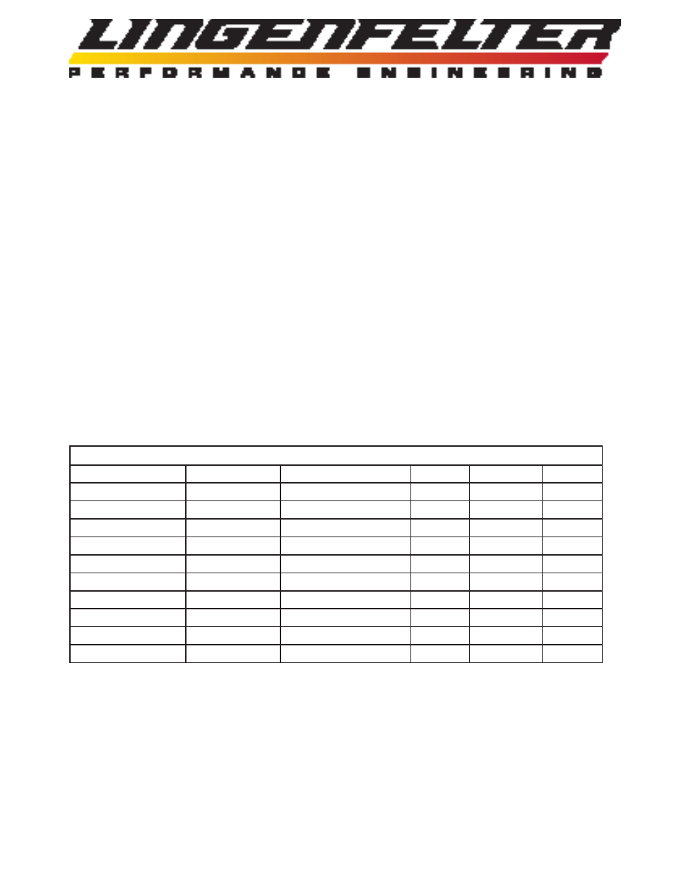
Table B
Common vehicle ECM/PCM tachometer signal wiring information
Vehicle
Year(s)
ECM/PCM location Pin
Wire color Circuit #
Camaro & Firebird 1996-1997
Connector C1 (Red)
13
White
121
Camaro & Firebird 1998
Connector C2 (Blue)
35
White
121
Camaro & Firebird 1999-2002
Connector C2 (Red)
10
White
121
Camaro
2010-2011
None (see page 7)
N/A
N/A
N/A
Corvette
1996
Connector C1 (Red)
13
White
121
Corvette
1997-1998
Connector C2 (Blue)
35
White
121
Corvette
1999-2003
Connector C2 (Red)
10
White
121
Corvette
2004
Connector C2 (Green) 10
White
121
Corvette
2005
Connector C1 (Blue)
48
White
121
Corvette
2006-2007
Connector C1 (Black) 48
White
121