Table a - wiring (also labeled on module), Settings, Rpm-002 – Lingenfelter L460040000 Lingenfelter RPM-002 RPM Activated Switch Instructions v2.3 User Manual
Page 3
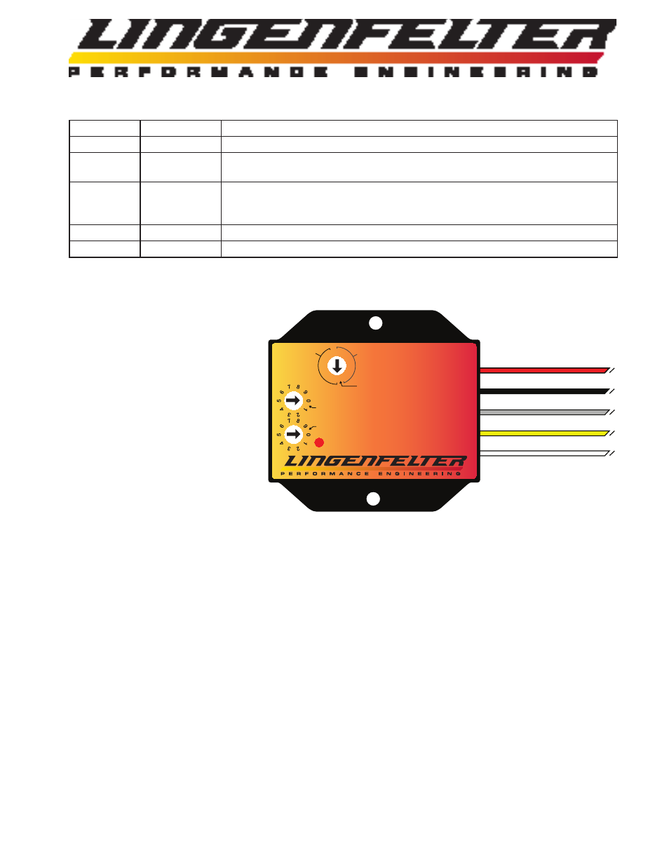
Table A - Wiring (also labeled on module):
Wire color
Label
Notes
White
Tach
This is the RPM input wire. This connects to your RPM signal wire.
Yellow
Normally Off
This is the normally open (off) activation wire. This wire connects to ground when
switch is activated. This connects to the ground side of the device you plan to activate.
Gray
Normally On
This is the normally closed (on) activation wire. This wire will open the ground path
when the switch is activated. This connects to the ground side of the device you plan to
control.
Black
Ground
Connects to a vehicle ground.
Red
+12 Vdc
Connects to a switched +12 volt DC source.
Settings:
•
Controlled by one sixteen position
switch and two ten position switches
o Single sixteen position switch for
selecting pulse per revolution count
(Input Signal Pulse Per Revolution
switch)
o First half of the range is the
Low Range (9,900 & below)
o Second half of the range is
for the High Range (10,000+
RPM)
o Two ten position switches for
selecting RPM (one above the other)
o RPM x1000
o RPM x100
Red LED:
o Comes on solid on start-up
o When active RPM is reached, LED will blink at 18 Hz (fast)
o Blinks at 2 Hz rate (slow) if RPM set below 500 RPM at start-up with outputs disabled
o Blink once per second for 30 seconds when ready to enter or exit Window Switch Mode
Notes:
o Changes to the RPM switch point settings must be done with the ignition off.
o The switch positions are only read on start up.
o The RPM Controlled Switch will not work at RPM levels below 500 RPM.
o The minimum difference between the high and the low mode when in Window Switch mode is 500 RPM.
o The RPM must drop 100 RPM below the RPM activation & deactivations settings to turn the circuit back on or off
(ie a 100 RPM hysteresis exists).
o
Do NOT submerge the module in liquid or directly wash the unit with liquid of any type! The
switches on the RPM-002 are sealed but are NOT rated for high pressure washing, use caution if
power washing near the RPM-002 module.
Page 2 of 8
Power
RPM-002
RPM Controlled
Ground - Black
Output Normally On - Gray
Output Normally Off - Yellow
Tach Input Signal - White
Switch
Input Signal Pulse
Per Revolution
RPM x1000
RPM x100
+12V Switched Power - Red
.5
1
2
3
4
5
1.5
2.5
.5 1
1.5
2
2.5
3
4
5
High Range
+10,000 Rpm
Low Range