Lingenfelter L460190108 Lingenfelter CTAP-001 Clutch & Throttle Activation Position Switch v1.7 User Manual
Page 5
Page
General Installation of the CTAP-001
• Disconnect the negative battery terminal.
• Connect black ground wire of CTAP to a suitable vehicle ground.
• Connect the red +12v power wire to a
switched and fused +12 volt DC source.
• Connect the purple analog signal input wire from the CTAP to the output signal wire from the sensor that will be used
to activate the CTAP, such as the Clutch Pedal Position (CPP) sensor, Throttle Position Sensor (TPS), Accelerator
Pedal Position (APP) Sensor, or other sensor that uses a 0-5 volt output signal.
• If you will be using the Normally Off (open) ground activation output, connect the yellow wire to the ground side of the
device you plan to activate.
• If you will be using the Normally On (closed) ground activation output, connect the gray wire to the ground side of the
device you plan to activate.
• If you will be using the Normally Off (open) +12 Vdc activation output, connect the orange wire to the +12 Vdc side of
the device you plan to activate.
• If the device you will be controlling draws more than 0.75 amps, make sure to control the device through a relay.
• Refer to the Programming instructions on page 5 to calibrate the CTAP-001 for the sensor signal that will be used to
activate it.
• With the device powered down, set the activation percentage (and the hysteresis if desired)
• Secure the CTAP-001 using the supplied hook and loop tape or using the supplied self taping screws.
Programming the CTAP-001
1. To put the CTAP-001 in programming mode, set all three switches
to zero and power up the module. The LED on the CTAP-001
should now be blinking GREEN.
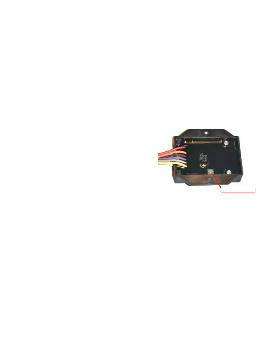
2. Using a Phillips head screwdriver, remove the back cover on the
CTAP-001 to access the green programming button.
3. With the vehicle keyed on, the engine off, and your foot off of
the pedal, press the green programming button on the back of
the CTAP-001. The CTAP-001 will now take the current closed
throttle voltage or released clutch voltage, depending on which
sensor you connected the CTAP-001’s purple analog input wire
to. The LED on the CTAP-001 will blink RED+GREEN at this
time.
4. Fully depress and then fully release the pedal that the CTAP-001 is connected to (throttle or clutch) two times. The
CTAP-001 will find the average of the two depressed voltages and then compare the average to the released voltage
to determine whether the calibration is valid. If the LED turns solid GREEN, the calibration was successful and is
programmed into memory. If the LED begins to blink RED, the calibration was unsuccessful for one of the following
reasons:
• The span between the closed throttle/released clutch signal and the wide open throttle (WOT)/depressed clutch
voltages must be at least 1.5 volts.
• The difference between the first WOT/depressed voltage and the second WOT/depressed voltage must be less
than or equal to 0.1 volts.
5. If an error occurs, simply power down the CTAP-001 and re-program the pedal position voltages.
6. If the programming of the CTAP-001 was successful, the LED will be solid GREEN until the input voltage exceeds
the user-defined set point. When the input voltage exceeds the user-defined set point, the LED will turn solid RED,
indicating that the outputs are active.
4.
Programming Button