LG Motorsports Track Box for C6, New Design User Manual
Page 7
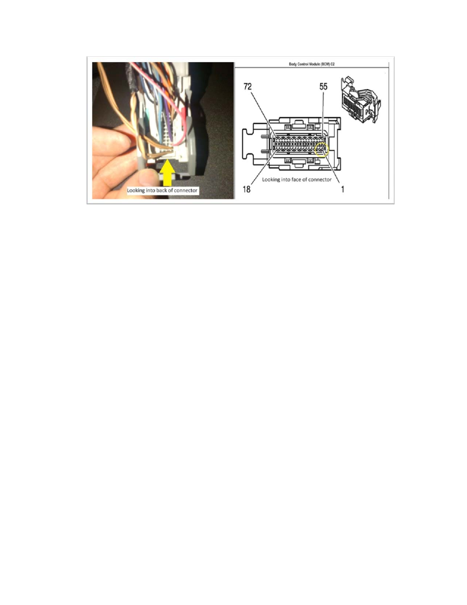
Figure 6
7. Once you have identified these four wires, they must be cut so that the TPMS controller can be
installed. Leave yourself a few inches of wire to work with.
8. Strip about ½ inch of insulation from the end of each wire and slide a piece of the included shrink
tubing over each end before connecting.
9. Wire pair (pin1 and pin2), and pair (pin3 and pin4) on the TrackBox harness come twisted together.
They can be un‐twisted a few inches to help installation, but not all the way. The red and black wire
may be un‐twisted as much as needed to install. The preferred method of installation is to solder
the wires as shown below, but the included wire crimp connectors can be used if required. Connect
the TrackBox harness into the vehicle harness as follows:
9 Step 1: Solder the two tan wires (pins 19 and 20) from the BCM connector together with
the blue wire (pin1) from TrackBox harness. See figure 7
9 Step 2: Solder the two tan/black wires (pins 1 and 2) from the BCM connector together with
the yellow/red wire (pin2) from the TrackBox harness. See figure 7
9 Step 3: Solder the two tan wires from the Vehicle Body Harness together with the blue wire
(pin3) from TrackBox harness. See figure 7
9 Step 4: Solder the two tan/black wires from the Vehicle Body Harness together with the
yellow/red wire (pin4) from TrackBox harness. See figure 7
9 Step 5: Connect the black wire (pin 5) to vehicle ground. There is a convenient ground
located under the kick panel near the BCM, shown in figure 8. This black ground wire can be
tapped into any of the existing black ground wires located in this area.
9 Step 6: Connect the red wire (pin6) to a constant 12V battery source. This wire must have
power even when the vehicle ignition is “off”. A convenient power source is located right at
the BCM connector shown in figure 9. The connector must first be unscrewed and then the