Rear panel – Dynacord PM2600 User Manual
Page 18
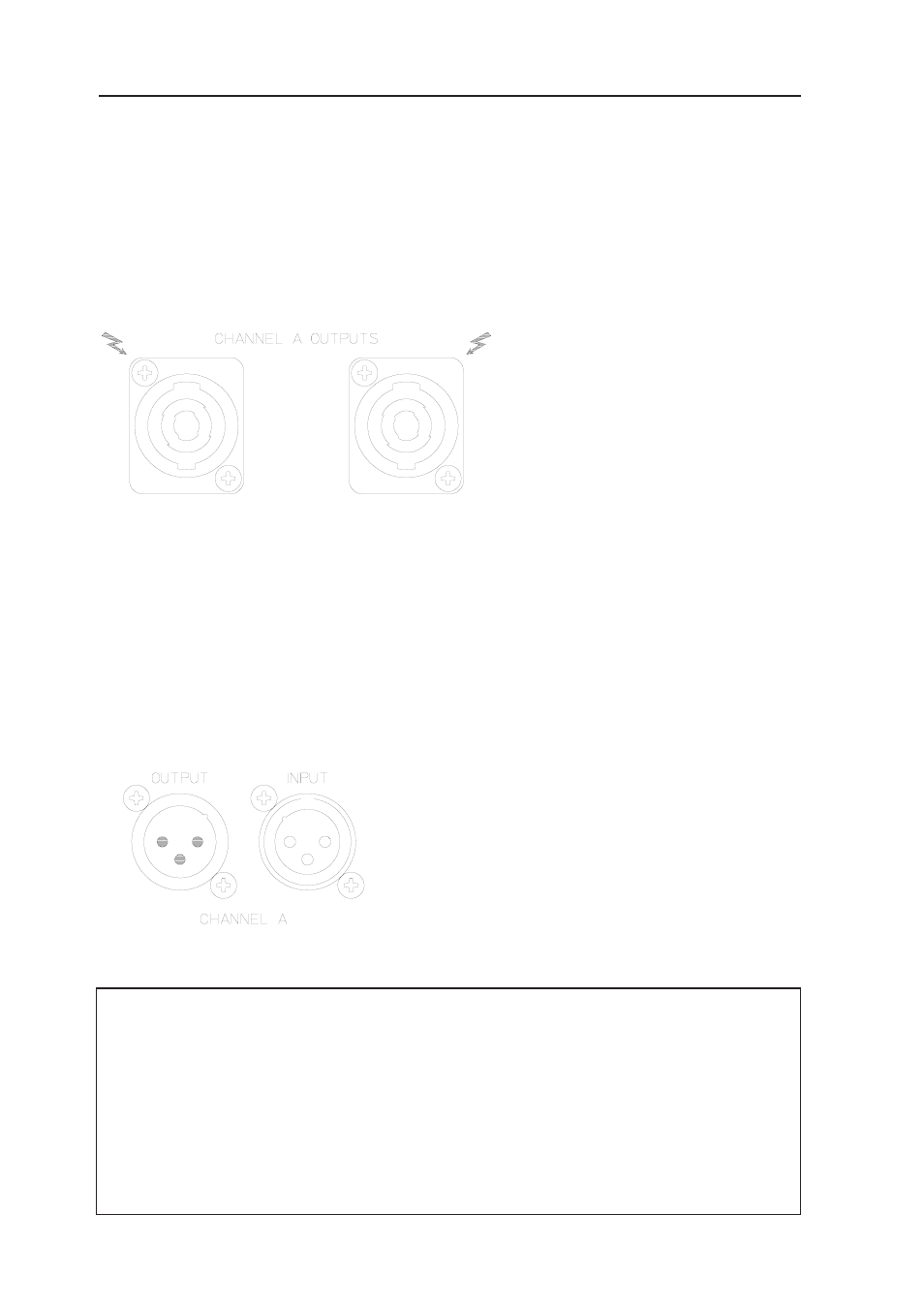
Power Amplifier Output Connectors
The power amplifier channels A (left) and B (right) are provided with 2 individual, output connectors that are
connected parallel. The outputs of the LO amplifier channels are present at PIN 1+ and PIN 1- while the
MID-HI amplifier channels are present at PIN 2+ and PIN 2-.
Pin-assignment of the output connectors
PIN 1+ = LO +
PIN 1- = LO -
PIN 2+ = HI +
PIN 2- = HI -
Power Amplifier Input Connectors
Each XLR-type input connector provides a parallel connected socket which offers the possibility to connect
the input signal through to additional external power amplifiers.
The power amplifier inputs are electronically balanced. Their pin-assignment is according to the IEC 268
standard.
Pin-assignment of the XLR-type input connectors
PIN 1: SHIELD
PIN 2: a, +
PIN 3: b, -
The inputs are electronically balanced.
REAR PANEL
Despite the fact that many mixing consoles provide XLR-type output connectors, of-
ten enough their actual signal path and pin-assignment is carried out unbalanced.
In case a mixing console with unbalanced outputs is connected to the PM2600, you
are presented with two alternatives: either bridging PIN1 and PIN3 of the power amp-
lifier input connectors or disconnecting the PIN3 at the plug of the connection cord.
When transmitting audio signals from unbalanced to balanced devices via PIN3 (b, -, “cold”)
and PIN2 (a, +, “hot”), this possibly results in humming and HF-interference noise, which
very likely might damage your power amplifier and/or the connected loudspeaker systems.
18