Rear panel, Qkp= oй~к=m~åéä – Lab.gruppen fP 6400 User Manual
Page 6
If the clip limiter is not engaged, it has an increased time constant, and it illuminates for a longer period.
(See page
6. Fan grill filters
Two grilles with foam filters are located on the front panel to prevent dust from entering the amplifier. For
easy cleaning of the filters the grilles are removable by simply pulling them off. The foam filters should
always be used.
7. Power switch
Turns mains power on or off. (See page
and
)
8. AC indicator
Indicates if AC voltage is present. Note: Electrically this indicator is located in front of the power switch.
9. AFS indicator
Indicates if the AFS
TM
(Automatic Fuse Saver) current limiter is activated.
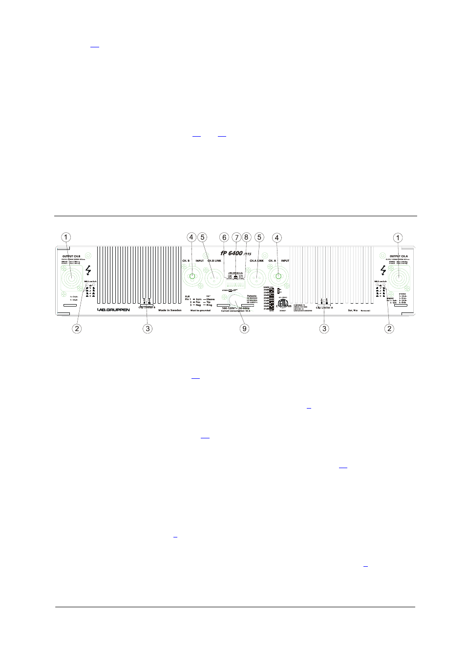
QKP= oЙ~к=m~åÉä=
Figure 2: Rear panel
1. Output / Speaker connector
The Speakon connector from Neutrik® may be unfamiliar to some users. A full description can be found
in the “Connections” section. (See page
)
2. Minimum load selector (MLS™) switch
These switches are used to select the maximum output power. (See page
)
3. Clip limiter switch
Turns the clip limiter on or off. (See page
)
4. Input signal XLR.
Neutrik® Combojack features also ¼” TRS phone jacks. (Pin 2 is “hot”, see page
)
5. Link output
XLR male connector connected in parallel to the female for linking the channel to another input.
6. Gain switch channel B
Three of the switches in the DIP switch selects the maximum gain of the channel to be either 20, 23, 26,
29, 32, 35, 38 or 41dB. (See page
)
7. Link/Bridge switch
Two of the switches in the DIP switch are used for Link and Bridge operation. (See page
)
i~ÄKÖêìééÉå== =
=
=
=
=
========================
R
rëÉê=j~ем~д===Сm=SQMMLNNRs======sÉêëáçå=NKM========OMMPJMOJOR=