Power consumption, Calculation, Skr= mçïéê=езелмгйнбзе – Lab.gruppen fP2600 User Manual
Page 12: Mains input power max output power
If however you wish to tie the signal ground to chassis, connect the XLR-connector’s shell lug to pin 1. In
the interest of safety never disconnect the earth pin on the AC power cord.
For all units that are FCC approved (radio interference), there is an AC mains filter. This filter needs the
chassis ground for reference, otherwise a current loop is formed via the signal ground.
Use the balanced input to avoid hum and interference.
SKR= mçïÉê=Езелмгйнбзе=
There are three ways to determine the power/current consumption of the amplifier:
First, the peak current draw at full output power. Under this condition the power will blow the mains
breaker within 30 seconds, or the amplifier will operate for less than 2 minutes before thermally
limiting. Therefore it is meaningless to state the input power at full power. The heat power at full power
will anyway be limited by the protection circuits. There is no audio program material producing steadily
full output power; it would be only sine wave for test purposes. It is more useful to state the current
draw in different loads and output power levels. These figures can be found on the specification sheet.
The current draw is measured in Ampere rms. This figure corresponds to the minimum value of the
mains fuse needed.
We recommend you to design the power distribution at least for the current at 1/8 power, and for 1/3
power for heavy-duty demands like discotheques, etc.
Second, the maximum expected average current under worst case program material, which is 1/3 of full
power according to the FTC standard. At this level the music will be in the state of constant clip and is
therefore the highest power level one can obtain without completely obliterating the program.
Last, the "regular operating power" as defined by the safety standard IEC 65/ANSI/UL 6500 and used
by a majority of safety agencies. The regular operating power is measured by using pink noise, and with
an average output power equal to 1/8 of full power. The one eighth of the total power is as loud as you
can play music while making some attempt to avoid obvious clipping. It also corresponds to a headroom
of 9dB, which is very low for regular audio program.
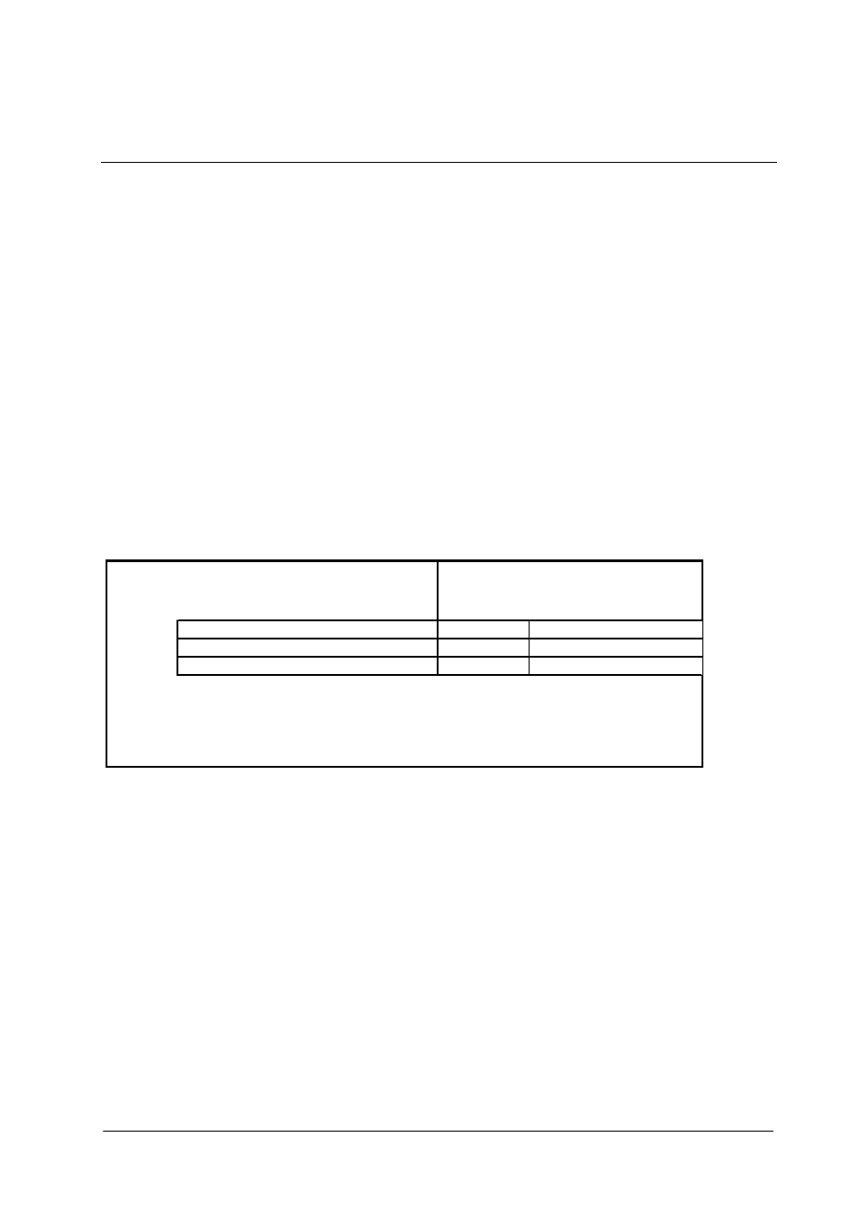
Power
1/3 Power
1/8 Power
Idle
[W]
note 1
note 2
fP 2600
8 ohms
2x
430
730
480
115
4 ohms
2x
840
1330
840
115
2 ohms
2x
1200
2200
1400
115
note 1
Average power with music as program source. The amplifier driven to clip level.
note 2
Normal music power with 9dB headroom, IEC standard power rating.
MAINS INPUT POWER
MAX OUTPUT POWER
Table 2
SKRKN= `~дЕмд~нбзе=
The heat power can be calculated as in the following example:
We consider a headroom of at least 5dB (1/3 of full power) and a 4 ohms load on an amplifier
producing 840 watts per channel. The 1/3 power per channel is accordingly 840 / 3 = 280 watts, and
total output 2 x 280 = 560 watts.
The power consumption according to the chart above is then 1330 watts. This chart shows the active
power consumption of the amplifier with different loads and power levels.
The heat power produced is the difference between the power consumption and output power:
1330 - 560 = 770 watts per amplifier.
i~ÄKÖêìééÉå== =
=
=
=
======================
========================
NN
rëÉê=j~ем~д===Сm=OSMMLNNR======sÉêëáçå=MKV========OMMPJMOJOP=