Appendices 20, Asymmetric loading data, E 12:2 – Lab.gruppen E 8:2 User Manual
Page 20: E series operation manual rev 2.0.0
14. Appendices
20
E SERIES Operation Manual rev 2.0.0
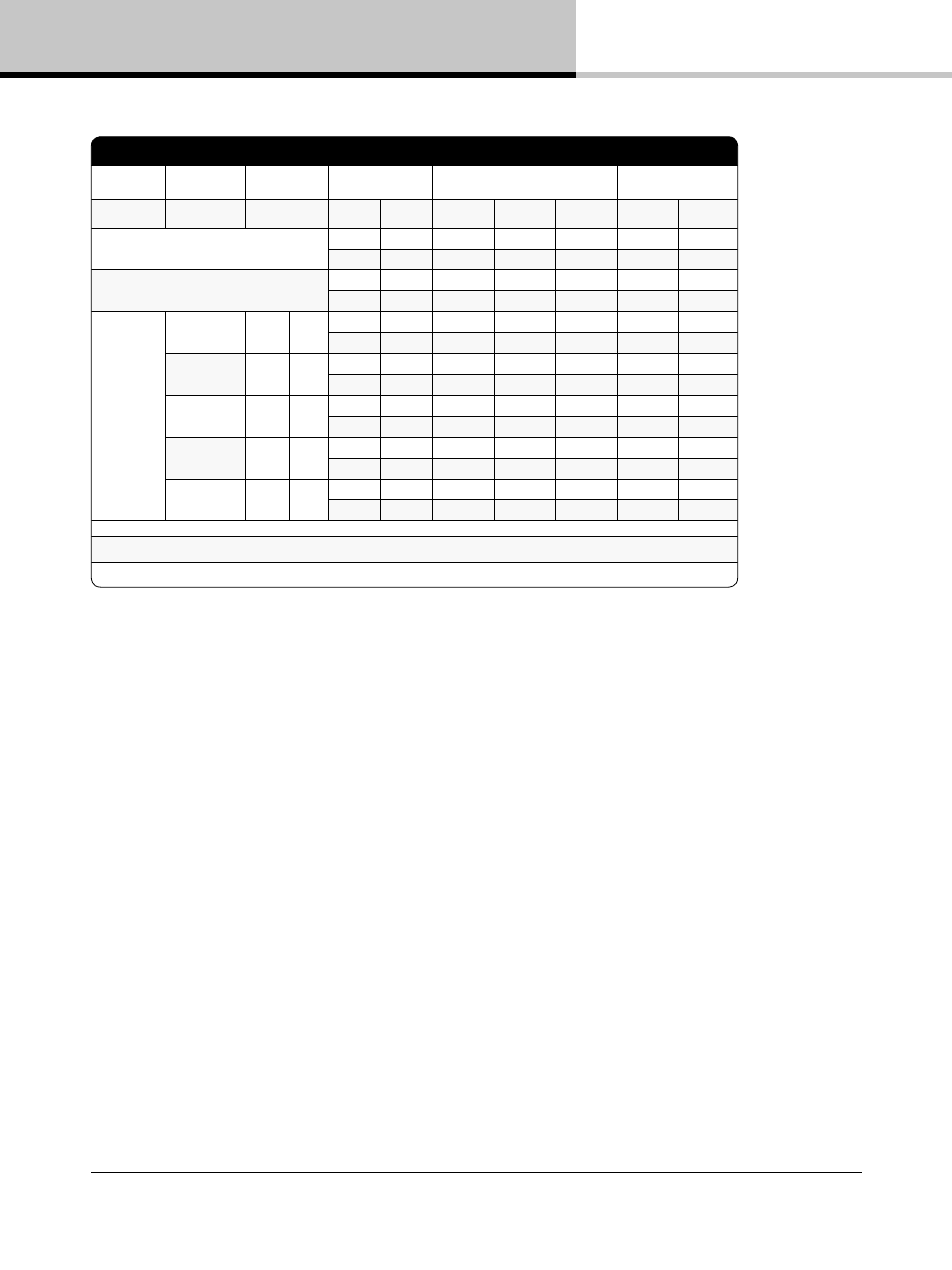
E 12:2
Level
Load
Output power
Line
current *2)
Watt *1)
Thermal Dissipation
120 VAC 230 VAC
In
Out
Dissi-
pated
BTU/hr
kCal/hr
Standby w. remote Power Off.
0.032
0.70
0
0.7
2.4
0.6
0.019
0.31
0
0.3
1.1
0.3
Power on, Idling
0.183
20.7
0
20.7
70.5
17.8
0.315
21.9
0
21.9
74.7
18.8
Pink Pseudo
Noise (1/8)
70 V / Ch.
600
x 2
1.8
210
150
60
205
52
2.9
223
150
73
248
62
16 ohms / Ch.
33
x 2
1.1
128
83
45
154
39
1.8
136
83
54
183
46
8 ohms / Ch.
600
x 2
1.8
209
150
59
202
51
2.9
219
150
59
237
60
4 ohms / Ch.
600
x 2
1.9
222
150
72
245
62
2.9
226
150
76
259
65
2 ohms / Ch.
600
x 2
2.0
249
150
99
337
85
3.1
252
150
102
349
88
*1) The amplifier’s PSU operates as a non-resistive load, so the calculation “Volts x Amps = Watts” would not be correct. Instead, measured and specified here
is what is known as the “Active Power” in the amplifier providing useful, real-world values of power consumption and heat dissipation.
*2) Current draw figures measured at 230 V. as well as 120 V. The efficiency is similar, but not identical for the two scenarios. The efficiency for 100 V mains is
very similar to that of 120 V.
14.3. Asymmetric loading data
Pages 21-23 following list possible settings and load combinations for asymmetric loading. For an explanation of
asymmetric loading, please see Section 13.4.3.
For values followed by an asterisk (*), use of an external limiter may be required for optimum performance.
All values assume amplifier is being driven by a signal from a professional mixing console or DSP unit. Values
will differ if driven by a consumer device, such as an iPod, with significantly lower output (2.71 dBu instead of the
required 4 dBu).