Attaching the lever, Attaching the caliper, Personal settings – Hope Tech M4 Brake User Manual
Page 6: Finger reach
6
2.3. Attaching the lever
Attach the lever assembly to the handlebars and route the caliper down to the fork disc mount or
along the frame to the rear disc mount. Take care to avoid situations that can damage the brake
hose when the bicycle is used such as trapping the hose within suspension fork or rear suspension
linkage movements, and also to avoid chaffing on the tire.
The lever will work in any position providing the master cylinder is not totally upside down. The
master cylinder need only be horizontal when bleeding the system.
2.4. Attaching the caliper
Before attaching the caliper ensure that the brake pads are fully retracted in the caliper. New
brakes will be supplied fully retracted, if you need to perform this operation yourself then on the
Closed 2 brakes turn the brake lever master cylinder screw adjuster anti clockwise (see Figure 4).
For the Mini and M4 brakes remove the pads to avoid damaging them and gently prise the pistons
back with a plastic tire lever (or similar).
The aim is to position the caliper central over the disc rotor using some of the supplied shim
washers between the caliper and disc mount to achieve the central positioning. This is trial and
error until the correct position is achieved.
When the caliper (and lever) are attached, secure the hose to the frame using ties or hose guides
and check for unrestricted handlebar movement and that the hose is not trapped or pinched.
2.5. Personal settings
Finger reach
This refers to the position of the lever blade relative to the bars. There are two procedures for
setting the reach depending on whether you have the Pro or Mini lever.
For the Pro lever slacken the
grub screw A (see Figure 2)
then adjust the position of the
lever using the adjuster screw
B. When the correct position is
achieved gently tighten the
grub screw A.
Figure 2
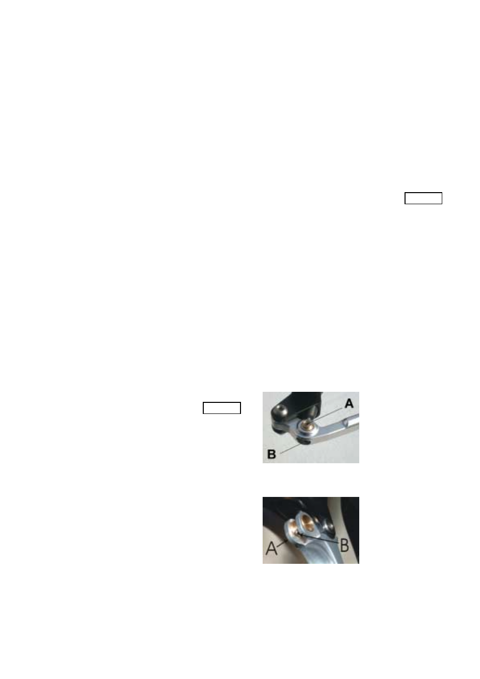
For the Mini lever slacken the
grub screw A (see Figure 3)
then adjust the position of the
lever using the adjuster screw
B. When the correct position is
achieved gently tighten the
grub screw A.
Figure 3