Hope Tech Race X2 Brake User Manual
Page 2
INSTALLATION STEPS
PERSONAL SETTINGS
BREAK IN PERIOD
WARRANTY
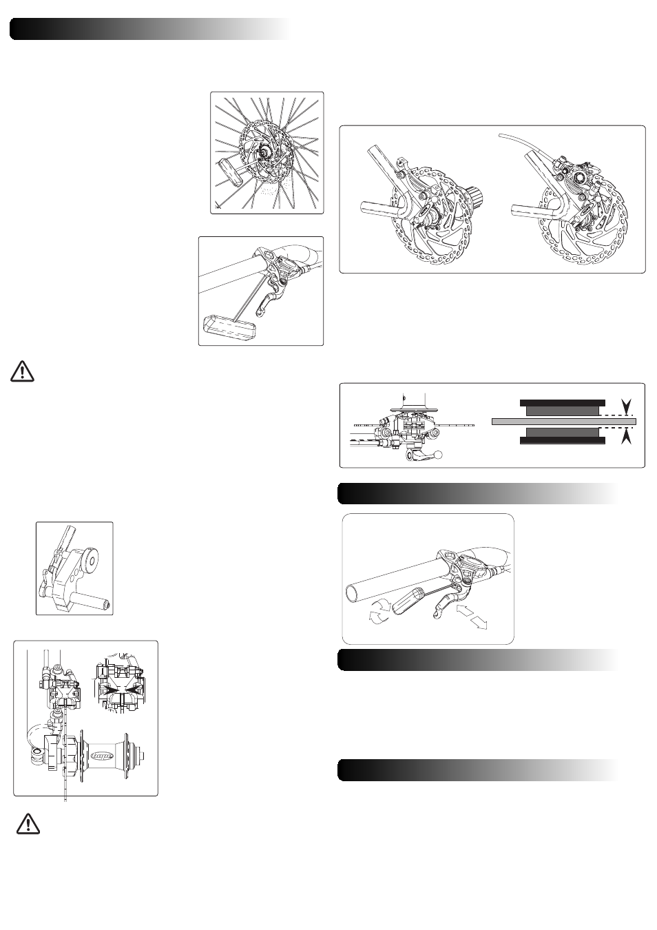
1. ATTACHING THE DISC TO THE HUB
2. ATTACHING THE LEVER TO THE BARS
3. ATTACHING THE CALIPER TO THE FORK OR FRAME
4. CENTRALISE THE PADS OVER THE DISC
RaceX2/08.09/ISS1
a) Attach the disc rotor to the hub using the
bolts provided with your disc type (6, 4 or 3 bolts)
b) Make sure that the laser marked arrow on
the disc is pointing in the same direction as the
forward wheel rotation.
c) Depending on the bolt type, using a Torx 25
driver or 5mm Allen key, tighten the disc bolts in a
cross pattern. Recommended tightening torque: 5
Nm for M5 bolts, 11Nm for M8 bolts.
Note: A mild engineering adhesive could be
used on disc bolts to prevent them unscrewing.
Do not use permanent adhesive.
a) Attach the lever assembly to the handle-
bars. When you are happy with the orientation
of the lever, tighten alternately the M5 clamp
bolts using a 4mm Allen key. Recommended
tightening torque: 4-5Nm.
b) Route the hose and caliper down to the
fork disc mount or along the frame to the rear
disc mount.
Avoid situations that could damage the brake hose and/or your bike frame
and components.
Note: In the first instance it is recommended that you install your brake as supplied
without disconnecting and routing the hose through frame guide (if present) or
attempting to shorten the hose.
The Race caliper is a postmount type. You will therefore need to use an adaptor
bracket to fit it on IS brake mounts.
a) Before attaching the caliper ensure
that the brake pads are fully retracted in
the caliper. If not, gently push the piston
back using a plastic tyre lever or
something similar. Beware not to
damage the pads. Take them off if
necessary. Push on the left hand side
pad backplate to push the right hand
side piston and vice versa.
b) Mount the wheel fitted with the
rotor, ensuring correct fitment in
dropouts.
c) Position the caliper on the mount
and slightly tighten the two M6 bolts.
d) At both front and rear of the
caliper, adjust its position so it is central
over the rotor (see arrows on fig 1) then
tighten the two M6 bolts using a 5mm
Allen key. Recommended tightening
torque 8Nm.
3.1 MOUNTING THE CALIPER ON POSTMOUNT TYPE MOUNTS
3.2 MOUNTING THE CALIPER ON IS TYPE MOUNTS
=
=
fig 1
Be careful not to get your
fingers caught in the disc when
following these steps.
Note : We do not recommend pumping the lever to push pads out to align caliper
at this point. See section 4 regarding the alignment of pistons.
On IS mount you will have to use an adaptor bracket to be able to fit the brake
caliper.
a) According to the rotor size and type of mounts, attach the suitable adaptor
bracket onto the brake tabs and tighten the two M6 bolts using a 5mm Allen key.
Recommended tightening torque 8Nm. Illustration fig 2.
b) Follow the same instructions as fitting the brake onto a postmount (see
previous section). Illustration fig 3.
This step is very important and mustn’t be ignored.
Gently pump the lever in order to bring the pads closer to the disc. One pad might
enter in contact with the disc before the other. If this happens, hold the disc against
the pad that is already in contact with the disc to allow the other one to move.
For an optimised lever feel, both pads must enter in contact with the disc at the
same time and allow the same clearance (see arrows) when retracted. The disc should
not be flexing at any time.
Before riding and before every ride, check the correct action of the brake and that
braking effort is applied as the lever is pulled.
To achieve the maximum braking performance, the new pads will need bedding
in. Please note that sintered pads take longer to bed in than organic pads.
To bed in the pads, ride a short distance whilst alternatively gently applying the
brake on and off without attempting to stop. This procedure will achieve good
braking performance but will reach its full potential after a few rides.
fig 2
fig 3
=
=
pad
pad
rotor
The Race master cylinder only
allows the adjustment of the
finger reach.
The finger reach adjustment
refers to the position of the lever
blade relative to the bars.
Use a 2mm Allen key, turn the
adjuster screw clockwise to
increase the reach and anti-
clockwise to reduce it.
+
-
-
+
Mainly on IS mounts, to ensure that the caliper
is properly aligned and to help avoid squealing or
bad lever feel - prior to fitting the brake, it is
important that the tabs of your fork or frame are
clear of any paint or burrs.
We recommend that you machine the tabs
using a suitable tool such as HOPE Spot Facing
Tool.
Please refer to the website videos and technical documents if you require more
information about setting up this brake system, servicing and maintenance.
www.hopetech.com
All Hope Technology disc brake systems are covered for one year from original
date of purchase against manufacturer defects in material and workmanship. Proof
of purchase is required. Products must be returned to the original place of purchase or
to Hope Technology to process any warranty claim.
This warranty does not cover any damage caused through mis-use or failing to
comply by the recommendations given in this manual.
This warranty does not affect your statutory rights.