Hope Tech V-Twin Brake User Manual
Page 2
INSTALLATION STEPS
PERSONAL SETTINGS
BREAK IN PERIOD AND MAINTENANCE
2. ATTACHING THE DISC TO THE HUB
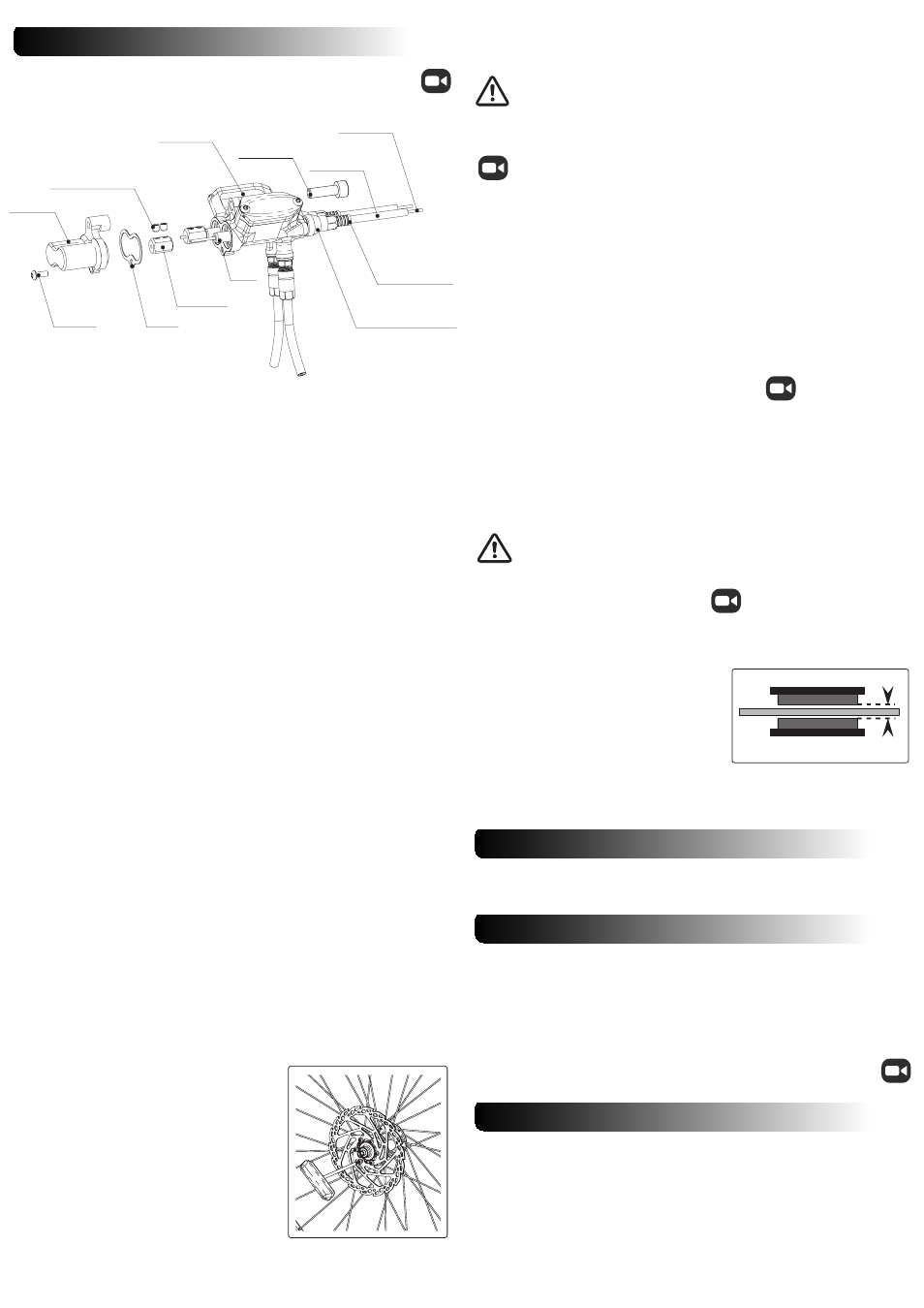
1. INSTALLING AND CONNECTING THE V-TWIN MASTER CYLINDER UNIT
3. ATTACHING THE CALIPER TO THE FORK OR FRAME
4. CENTRALISE THE PADS OVER THE DISC
V-Twin X2/10.11/ISS1
3.2 MOUNTING THE CALIPER ON IS TYPE MOUNTS
=
=
pad
pad
rotor
WARRANTY
All Hope Technology disc brake systems are covered for one year from original
date of purchase against manufacturer defects in material and workmanship. Proof
of purchase is required. Products must be returned to the original place of purchase or
to Hope Technology to process any warranty claim.
This warranty does not cover any damage caused through mis-use or failing to
comply by the recommendations given in this manual.
This warranty does not affect your statutory rights.
3.1 MOUNTING THE CALIPER ON POSTMOUNT TYPE MOUNTS
a) Before attaching the caliper ensure that the brake pads are fully retracted in the
caliper. If not, gently push the piston back using a plastic tyre lever or
something similar. Beware not to damage the pads. Take them off if
necessary. Push on the left hand side pad backplate to push the right hand side
piston and vice versa.
b) Mount the wheel fitted with the rotor,
ensuring
correct
fitment
in
dropouts.
c) Position the caliper on the mount and slightly tighten the two M6 bolts.
d) At both front and rear of the caliper, adjust its position so it is central over
the rotor then tighten the two M6 bolts using a 5mm Allen key. Recommended
tightening torque 8-9 N.m.
Be careful not to get your fingers caught in the disc when following
these steps.
We do not recommend pumping the lever to push pads out to align
caliper at this point. See section 4 regarding the alignment of pistons.
a) Attach the disc rotor to the hub using the
bolts provided with your disc type (6, 4 or 3
bolts).
b) Make sure that the laser marked arrow on
the disc is pointing in the same direction as the
forward wheel rotation.
c) Depending on the bolt type, using a Torx 25
driver or 5mm Allen key, tighten the disc bolts in a
cross pattern. Recommended tightening torque :
5-6 N.m for M5 bolts, 11-12 N.m for M8 bolts.
Note : A mild engineering adhesive could be
used on disc bolts to prevent them unscrewing.
Do not use permanent adhesive.
1. Remove the existing brakes if present leaving handlebar levers and cables in place.
2. Cut a clean edge on both inner cables before removing it from existing outer cable
to make it easier for re-fitting.
3. Apply the brake lever to gain access to remove both inner cables from the lever
assembly.
4. Install the support plate on steerer tube making sure the master cylinder doesn’t
touch the stem when mounted. The plate mounts between the top headset cover
and the stem. You may need to use some provided headset spacers to achieve the
most suitable position for the master cylinder.
5. Remove the rear end cover and its gasket.
6. Install the V Twin master cylinder assembly under stem and fasten it to the support
plate using the M5 bolt and provided nut whilst the rear end cover is removed.
7. Nicely route the brake cable outer into the V-Twin master cylinder assembly and
cut it so the cable outer sits in the screw on cable tension adjusters. At this point pay
attention to which side of the V Twin master cylinder assembly the front and rear
calipers are attached. Depending if you want the front brake to be operated by the
RH or LH lever route the cable outer to the correct side of the master cylinder.
8. Now re-feed the brake cable inner through the cable outer and throughout the
piston.
9. When the brake cable is coming out of the rear of the V Twin master cylinder
assembly, slide the brass brake cable lock onto the inner brake cable.
10. Whilst pulling the inner brake cable out of the rear of the master cylinder push
the brake cable lock against the piston shoulder taking care NOT to push the piston
itself.
11. When the brass brake cable lock is sitting flush against the piston face gently
tighten the cable with the 2x M4 grub screws.
12. Make sure the brass brake cable lock is sitting against the piston face or very close
to it (1mm clearance maximum)
13. If you have achieved step 12 then proceed to tighten more firmly the brass cable
lock’s 2x M4 grub screw. If not go back to step 10.
14. The screw on cable tension adjuster would allow to take out any play if there is a
gap between the piston face and the brass brake cable lock. If you wish you can leave
the gap and this would result in more free brake lever stroke. But you must always
have a small amount of play or the pads may not self adjust and also pump up when
warm resulting in the brake locking on.
15. Repeat the operations 8 to 14 for the second brake cable.
16. When both brake cables are in place and firmly tightened cut the excess brake
cable. Leave a maximum of 2mm sticking out of the brake cable lock or it may
prevent the rear end cover sitting in place correctly.
17. Re install the rear end cover and its gasket and screw on the M3 torx screw.
18. Then finally bolt the V-Twin master cylinder assembly fitted with its end cover to
the support plate.
On IS mount you will have to use an adaptor bracket to be able to fit the brake
caliper.
a) According to the rotor size and type of mounts, attach the suitable adaptor
bracket onto the brake tabs and tighten the two M6 bolts using a 5mm Allen key.
Recommended tightening torque 8-9 N.m.
b) Follow the same instructions as fitting the brake onto a postmount (see
previous section).
This step is very important and mustn’t be
ignored.
Gently pump the lever in order to bring the
pads closer to the disc. One pad might enter in
contact with the disc before the other. If this
happens, hold the disc against the pad that is
already in contact with the disc to allow the
other one to move.
For an optimised lever feel, both pads must
enter in contact with the disc at the same time
and allow the same clearance (see arrows)
when retracted. The disc should not be flexing
at any time.
Only the brake cable tension is adjustable. The rear end cover must be removed to
proceed. See then step 14 of the master cylinder installation paragraph.
Please refer to the website videos and technical documents if you
require more information about setting up this brake system, servicing
and maintenance. www.hopetech.com / Tech support section
Before riding and before every ride, check the correct action of the brake and that
braking effort is applied as the lever is pulled.
To achieve the maximum braking performance, the new pads will need bedding in.
Please note that sintered pads take longer to bed in than organic pads.
To bed in the pads, ride a short distance whilst alternatively gently applying the
brake on and off without attempting to stop. This procedure will achieve good
braking performance but will reach its full potential after a few rides.
About maintenance tips refers to our “how to” videos on the website.
For brake bleeds use only dot 5.1 or dot 4 brake fluid from a clean container.
Avoid situations that could damage the brake hose and/or your bike frame
and components
Note: In the first instance it is recommended that you install your brake as supplied
without disconnecting and routing the hose through frame guide (if present) or
attempting to shorten the hose.
At a later date you can shorten the brake hose if required. For this operation,
follow the intructions in the how to videos of our website.
Route the hose and caliper down to the fork brake mount or along the frame to the
rear brake mount.
M3 screw
M3 screw
Gasket
Gasket
Brass brake
Brass brake
cable lock
cable lock
M4 grub screw (x2)
M4 grub screw (x2)
V-Twin MCyl
V-Twin MCyl
Assembly
Assembly
Rear
Rear
end cover
end cover
Piston
Piston
Brake cable
Brake cable
inner
inner
Brake cable
Brake cable
outer
outer
Cable outer stop
Cable outer stop
Screw on
Screw on
Cable tension adjuster
Cable tension adjuster
M5 x 16
M5 x 16
cap screw
cap screw