Physical connections – Hatteland Display 19 inch - HM 19T14 MMD (TEMPEST) User Manual
Page 15
15
IND100133-42
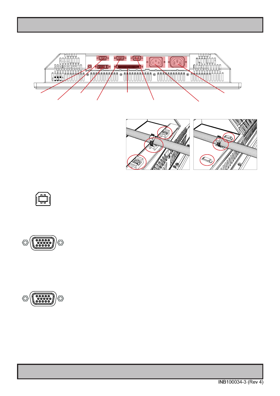
RGB IN
AC Power Input
Multifunction Conn.
Connection area of unit (illustration)
Cable Tension
To reduce tension of the cables you connect,
secure them with a cable tie to the base mounted
clamp or to the chassis hinges.
For certain units a base mounted clamp is
available (FIG 1). For other models a hinge in
the chassis is available (FIG 2).
FIG 1
FIG 2
Physical Connections
AC Power Ouput
USB I/O
DVI-I IN
RGB OUT
DC Power Input
USB I/O:
This USB TYPE B connector is not connected for the TEMPEST model and has no functionality.
RGB IN:
Connect the VGA cable to the D-SUB 15P Connector (female). Secure the VGA cable to the hex spacers provided on
the unit and make sure you do not bend any of the pins inside the connector when connecting. Connect the other end
of the cable to the VGA connector on your equipment and secure it.
RGB OUT:
RGB OUT enables a direct clone of the incoming VGA (RGB1) signal. Connect the cable to the D-SUB 15P Connector
(female) and secure it to the hex spacers provided on the unit. Connect the other end to your equipment and secure
it. Note that DVI inputs is NOT cloned, even though if the DVI-I connector has been configured with the DVI-I > RGB
adapter to use a RGB signal as input.