Hanna Instruments BL Series Pumps User Manual
Page 8
15
14
It is recommended that the system be con-
nected to a power line/leg equipped with a
circuit breaker of 1 Amp.
Permanent Connection using 3/8"PVC pipe
All piping for the
pump feed and dis-
charge should be
plumbed to the loca-
tion of the pump.
The threads on both
valve assemblies al-
low the use of stan-
dard 3/8" (European)
pipe fittings for per-
manent pipe connec-
tions.
The foot valve as-
sembly (HI 721005)
should always hang
vertically and not lay
horizontal on the
bottom of the tank
or drum.
A vertical assembly
will ensure that the
valve is positioned
properly and prevent
loss of prime.
For the U.S. standard installations, use PVC
adapters to connect the suction and dis-
charge valves to the PVC pipe.
Hose Connections
• Cut a long enough
section of the
hose to reach the
suction valve of the
pumphead from
U
NION
C
ONNECTION
A
DAPTER
D
ISCHARGE
V
ALVE
P
UMP
S
UCTION
V
ALVE
A
DAPTER
F
OOT
V
ALVE
F
ILTER
-
Diagram for Rigid Pipe Hose
• The pump should be placed in a conven-
tional location that will allow easy access
to the control and connections. It should be
placed so that regular visual inspections of
the connections and hoses are facilitated.
Vertical Surface Mounting
Once you have selected the best installation
site, simply screw or bolt the unit into a wall
or mounting panel above the chemical feed
tank.
The 4 mounting screw holes on the pump
will accommodate up to a 5 m m (3/16")
screw or bolt (remember to use heavy screws
or bolts to secure the system).
Be sure you do not over tighten and cause
excessive stress on the mounting holes.
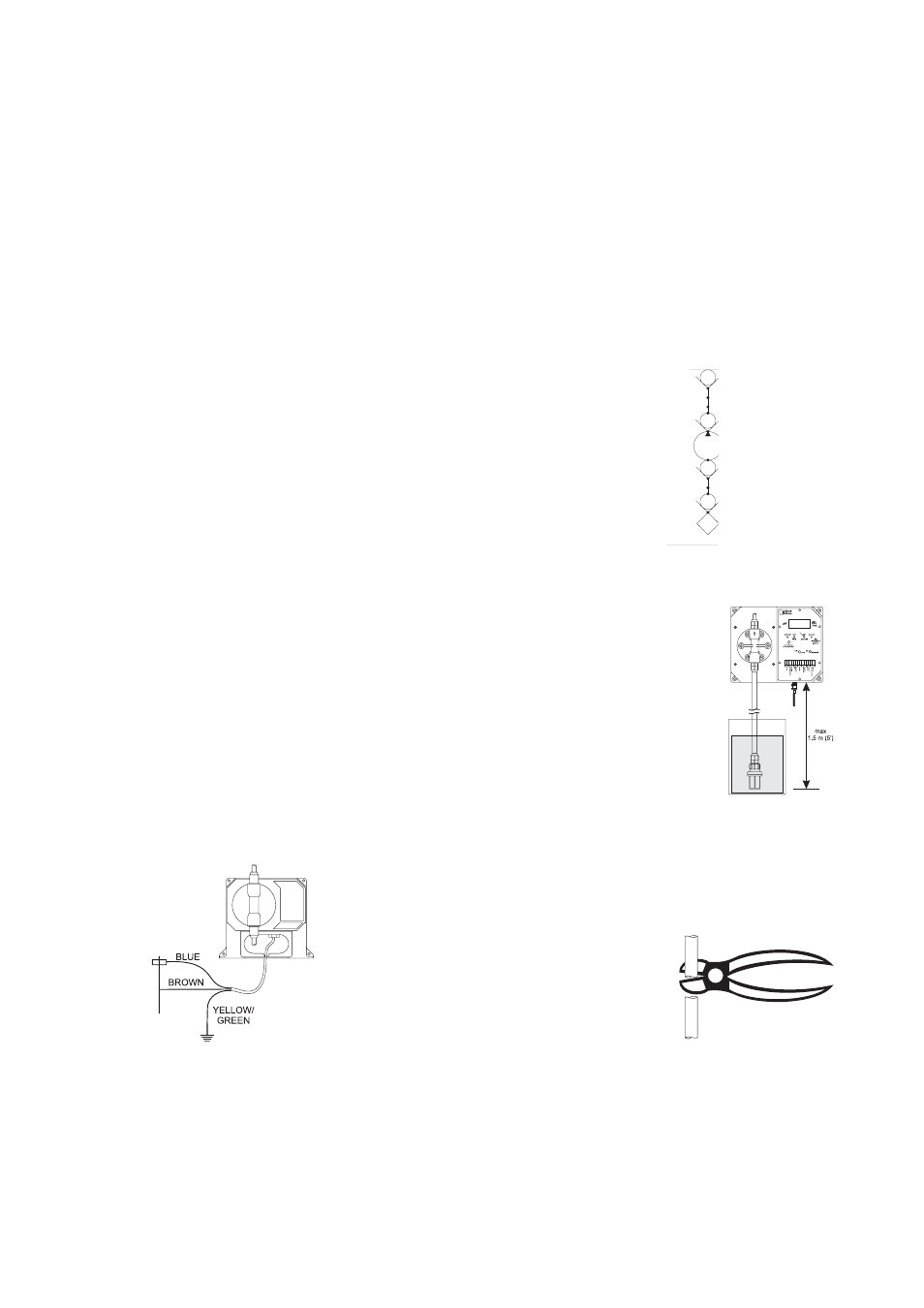
Electrical Connections
Note: All cables must be according to local
electrical codes.
For safety of the users, the pump has to
be grounded.
The pump should be connected to a single
phase power source.
Color coding for wires:
Blue - Live
Brown - Neutral
Yellow/Green - Ground (earth)