Setup mode – Hanna Instruments mV 602 Series User Manual
Page 6
11
10
SETUP MODE
pH 502 and mV 602 offer a multitude of possibilities from
ON/OFF or PID dosage to analog recorder output and from
alarm to selftest features.
The Setup Mode allows the user to set all needed character-
istics of the meter.
The setup mode is entered by pressing SETUP
and entering the password when the device
is in idle or control mode.
Generally speaking, if the password is not inserted the user
can only view the setup parameters (except for password)
without modifying them (and the device remains in control
mode). An exception is certain setup items, or flags, which
can activate special tasks when set and confirmed.
Each setup parameter (or setup item) is assigned a two-
digit setup code which is entered and displayed on the
secondary LCD.
The setup codes can be selected after password and CFM
are pressed. When CFM is pressed, the current setup item is
saved on EEPROM and the following item is displayed.
Whenever LCD is pressed, the de-
vice reverts back to control mode.
The same is true when CFM is
pressed on the last setup item.
The possible transitions in setup mode are the following:
ENTERING THE PASSWORD
• Press SETUP to enter the setup mode. The LCD will display
“0000” on the upper part and “PAS” on the lower. The first
digit of the upper part of the LCD will blink.
• Enter the first value of the pass-
word by the or keys.
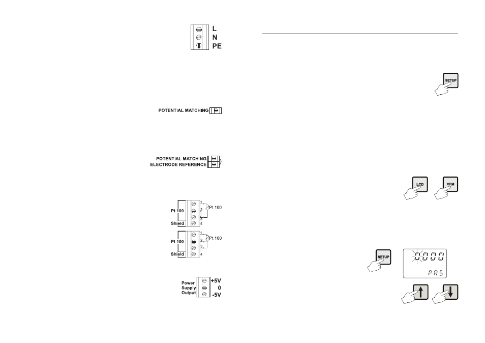
• Power Supply: Connect a 3-wire power cable
to the terminal strip, while paying attention
to the correct line (L), earth (PE) and neu-
tral (N) terminal connections.
Power: 115 Vac - 100 mA / 230 Vac - 50 mA.
Line Contact: fused inside 400mA.
PE must be connected to ground; leakage current 1mA.
• Electrode: Connect the pH or ORP electrode to the BNC
socket (#10 at page 7).
To benefit from the differential input, connect the proper
electrode wire (if available) or a cable with a potential
matching pin (grounding
bar) to the relevant termi-
nal (#9 at page 7).
Note
When it is not possible to immerse the Potential Matching Pin
together with the pH electrode in the solution, disable the
differential input by connecting the Connection for Potential
Matching Pin (#9 page 7) with the Connection for Electrode
Reference (#8 on page
7) with a jumper wire.
• Pt 100 Terminals: these contacts (#7 at page 7) connect
the Pt 100 temperature sensor for automatic temperature
compensation of pH measurement. In the case of shielded
wire, connect the shield to pin 4.
In the case of a 2-wire sensor con-
nect the Pt 100 to pins 1 and 3,
and short pins 2 and 3 with a
jumper wire.
If the Pt 100 has more than 2
wires, connect the two wires of one
end to pins 2 and 3 (pin 2 is an
auxiliary input to compensate for
the cable resistance) and one wire
from the other end to pin 1. Leave
the fourth wire unconnected, if present.
• Power Supply Output: these terminals
provide +5 Vdc and -5 Vdc signals to
supply power to amplified electrodes.
Note
All cables connected to rear panel should end with cable lugs.