Service procedures, Continued – Desa H.S.I. User Manual
Page 8
112846-01A
8
For more information, visit www.desatech.com
For more information, visit www.desatech.com
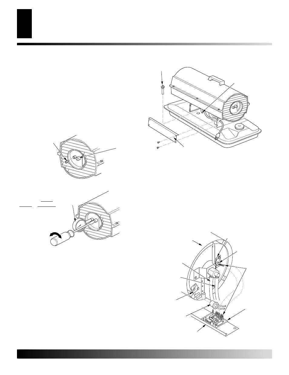
IGNITOR
1.
Remove upper shell and fan guard (See Upper Shell Removal,
page 7).
2.
Remove fan (see page 7).
3.
Remove 4 side cover screws with a 5/16" nut driver. Remove
side cover (see Figure 10).
4.
Disconnect ignitor wires from ignition control assembly (see
Figure 11). Pull the ignitor wires up through the hole in the
lower shell.
5.
Disconnect fuel line hose and air line hose. Remove photocell
from photocell bracket (see Figure 11).
Figure 11 - Disconnecting Ignitor Wires from Ignition Control
Assembly
Combustion
Chamber
Photocell
Bracket
Photocell
Assembly
Air Line Hose
Fuel Line Hose
Ignitor Wire
Ignitor
Nozzle Adapter
Bracket
Ignition
Control
Assembly
Side Cover
Figure 10 - Fuel Filter Removal
Fuel Filter
and Bushing
Side Cover
Upper Fuel Line
SERVICE PROCEDURES
PUMP PRESSURE ADJUSTMENT
1.
Remove pressure gauge plug from filter end cover (see Figure 8).
2.
Install accessory pressure gauge (part number HA1180).
3.
Start heater (see Operation, page 4). Allow motor to reach
full speed.
4.
Adjust pressure. Turn relief valve to right to increase pressure.
Turn relief valve to left to decrease pressure. See specifica-
tions correct pressure for each model (see Figure 9).
5.
Remove pressure gauge. Replace pressure gauge plug in filter
end cover.
SERVICE PROCEDURES
Continued
Figure 8 - Pressure Gauge Plug Removal
Pressure
Gauge
Plug
Pressure
Gauge
Figure 9 - Adjusting Pump Pressure
Relief
Valve
Pump
Model
Pressure
55
3.4 PSI
60
3.4 PSI
FUEL FILTER
1.
Remove side cover screws using 5/16" nut-driver.
2.
Remove side cover.
3.
Pull upper fuel line off fuel filter neck (see Figure 10).
4.
Carefully pry bushing and fuel filter out of fuel tank (see Fig-
ure 10).
5.
Wash fuel filter with clean fuel and replace in tank.
6.
Attach upper fuel line to fuel filter neck.
7.
Replace side cover.