Hall Research SW-VRS232-2S User Manual
Page 9
7
Model SW-VRS232
2. Drill pilot holes where indicated on the stencil, using a 1/16” bit.
3. Screw Selection: Be sure to use the appropriate kind of screw for the surface
the unit is being mounted to. It is recommended to use a 1” long, #6 screw
(shank = 0.138, or about 9/64”).
4. Remove the stencil and install screws, leaving 0.19” (about 3/16”) of the
threads protruding (when measuring, do not include the screw head).
CAUTION:
Improper installation of mounting screws may result in
damage to unit. A screw protruding 0.40” (or more
than about 3/8”) will hit the circuit board, causing
possible damage. Additionally, the unit will not be
securely mounted, which may cause it to fall. Measure
screws for proper height prior to securing the unit.
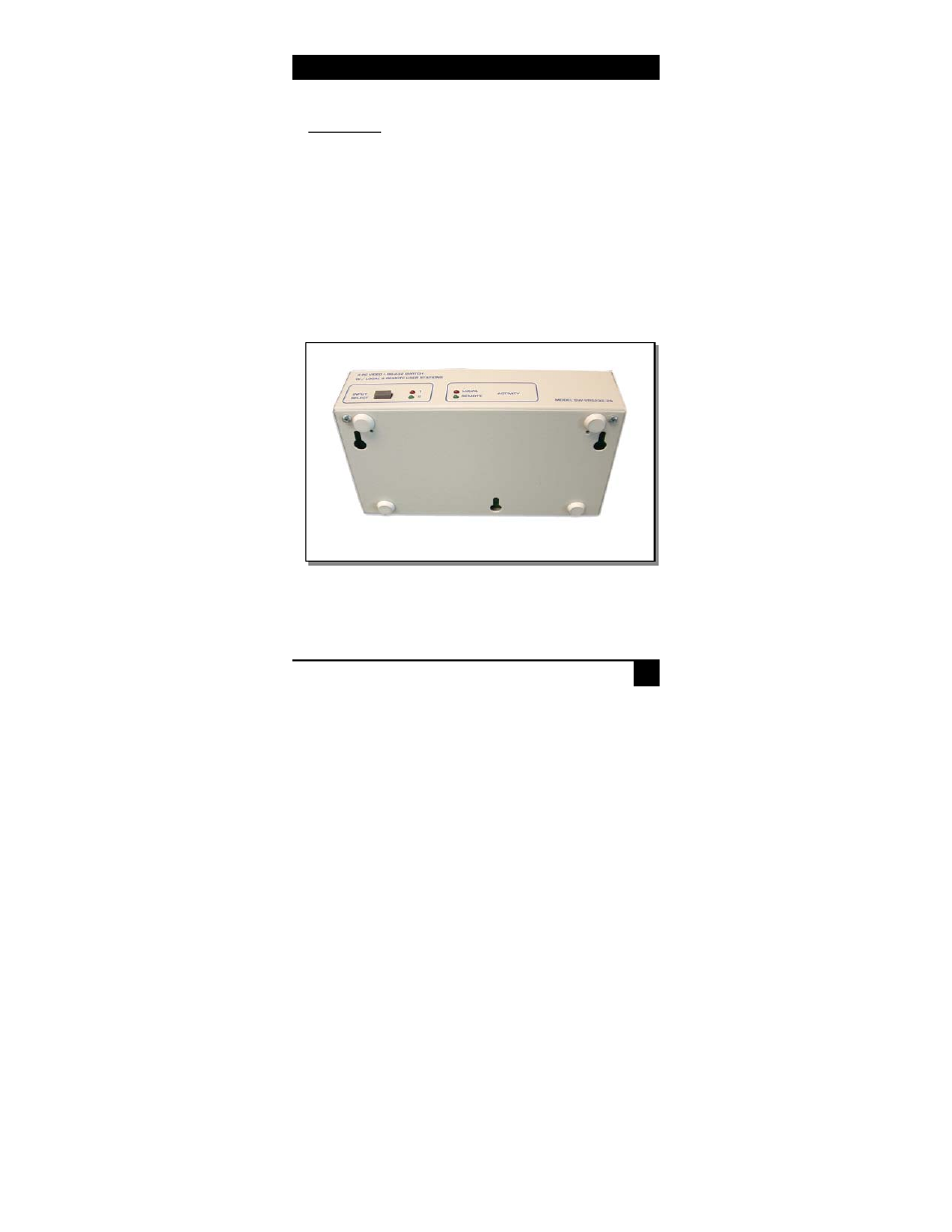
SW-VRS232-2S Bottom View of Keyhole Mounts