Hall Research SW-VRS232-2S User Manual
Page 7
5
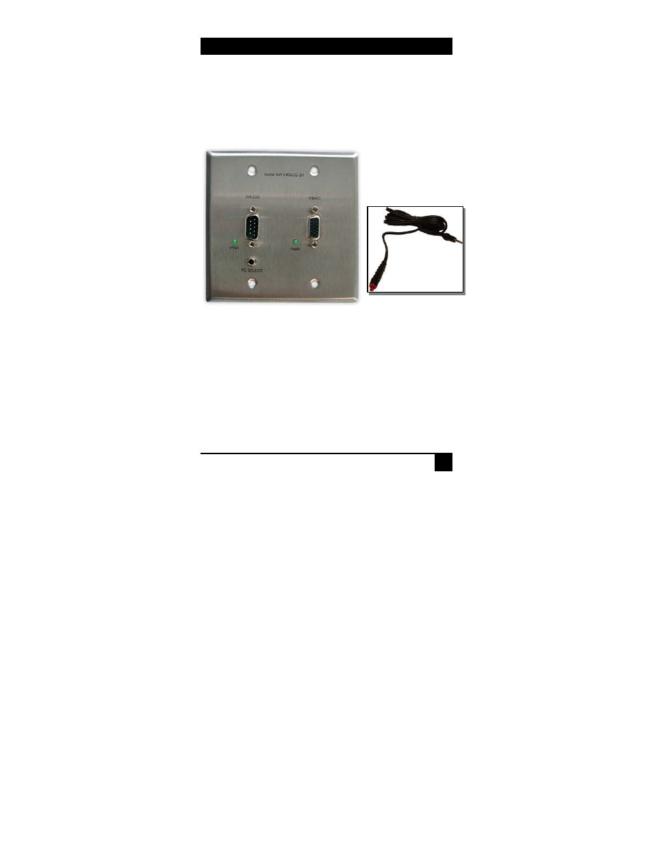
Model SW-VRS232
2.2 Connecting the SW-VRS232-2R
1. If the optional 2-gang wall plate receiver (Model SW-VRS232-2R) will be
used, make sure to plug the Catx cables to the correct connector on both ends.
The unit is designed so that there is no damage if the cables are cross
connected since the power distribution uses the same pins in the UTP cable, but
if plugged incorrectly, the system will not work.
2. The remote user can switch between PC’s by using an optional push-button
switch, (Model # PB-SW). When pushed, an LED in the switch will blink to
indicate which PC is selected – once for PC 1, twice for PC 2.
3. Video compensation is set with the receiver running, prior to installing the
wall plate. Adjustment is made via a small potentiometer on the back of the
video board, labeled “CABLE ADJ”. Start with the compensation pot turned fully
CCW (no compensation); then gradually increase until video image bleeding is
eliminated. See Section 3 for cable type and video considerations.
Figure 2.3
SW-VRS232-2R
Receiver
PB-SW