Important – Hall Research URA-RS232-C User Manual
Page 7
7
Projector Controller Programmable Serial Device
Uploading commands to the URA-RS232
After you have loaded a configuration file
containing your “ON” string and “OFF” string or you
have created your “ON” string and “OFF” string you
are now ready to upload the “ON” and “OFF”
strings to the URA-RS232.
Connect the URA-RS232 to the PC’s comm. port
you selected earlier via the supplied programming
cable. The supplied programming cable is a 6’
cable that has a female DB-9 connector that
connects to the PC and the other end is a male mini-stereo connector that
plugs into the URA-RS232
.
Important!
You may need to use a crossover
serial cable (also know as a NULL-
modem cable) to connect the URA-
RS232 to the device you want to
control.
There are 2 types of serial devices:
1. DTE (Data Terminal Equipment) ex. Computer/ PC
2. DCE (Data Communication Equipment) e.g. Serial controlled
projector, modem, or the URA-RS232.
DTE devices talk directly to DCE devices. If you have 2 DTE devices trying to
talk, they need a crossover serial cable connecting them. In the same way if
you have 2 DCE devices trying to talk, they will need a crossover serial cable
connecting them as well. Generally DTE devices will have a male DB9
connector and DCE devices will have a female DB9 connector. You will
notice that the serial cable included with the URA-RS232 has a female DB9
connector. This indicates that the URA-RS232 is a DCE device, which is why
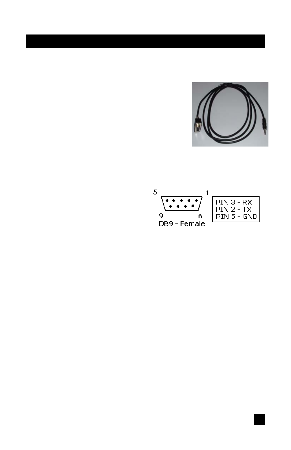
it will connect directly to a computer/PC serial port. When you are done
uploading the “ON” and “OFF” strings to the URA-RS232, you will need to
use a crossover or straight through serial cable to connect the URA-RS232 to
your serial device depending on what type of serial device you are trying to
control. Here is the pinout for the URA-RS232.
Power on the URA-RS232 and click the “Upload” button.
A message box will tell you when the upload has completed
.