Grandview LF-MIRCI(Recessed-Ceiling Series) User Manual
Page 7
9
7.Please ensure the hexagon surface of nut and inside surface of casing are at the same level (figure 16); stay the
pressing piece on the nut (figure 17-18)
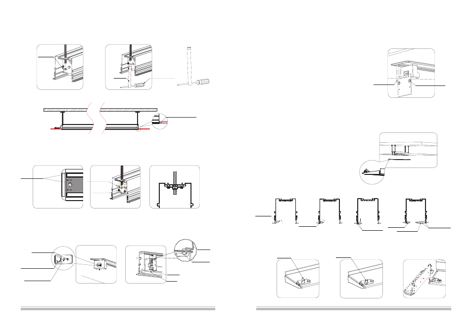
8. Insert the external infrared receiver to EXT IR hole(figure 18),
infrared receiver must be ready for control, then install the power box back to bracket .
(note: ensure the power box is buttoned on the hanger of bracket) (figure 19).
because of the recessed mount, the external
Figure16
Figure18
Figure17
Two surfaces are
at the same level
Figure
18
EXT CTRL
(
)
Dry
Contact/RS232
EXT IR(
)
External
Infrared Receiver
TRIG(
)
Trigger
Figure
19
Figure15
M12 Screw
Wrench
Not provided
(screwdriver
can replace)
Align the ornament
board with ceiling
Figure13
Figure14
Wrench
Bracket
Button
Note: the power box must be
buttoned on the hanger of bracket.
Power Box
Screw
1) Insert the baffle
to top groove.
2) Stay flat the baffle,
and clip it to low groove.
Low Groove
Two surface at
the same level
3) Press the baffle slightly
and align it with ceiling board.
4) The installation of
large baffle is the same.
Large Baffle
Small Baffle
Two surface at
the same level
6
10. Install the large and small baffle
1)Please ensure the security lock is unlocked (figure 20 and 22).
2)Install the large and small baffle (figure 21)
3)Unlock the security lock of baffle (figure 23), insert the plug of security to a
hole of end cap (figure 24), if the baffle can not move up that please align
baffle with ceiling board.
Note:
Recessed motorized screens under 120” utilize both a large and
small trim cover. Recessed motorized screens above and
including 120” utilize only one large trim cover.
All Tab-tensioned Recessed motorized screens utilize only one
largetrim cover.
Top Groove
Figure21
Figure22
Figure23
Figure24
Note: the upward instruction shows us installation of external control system, if the users want to
add other control systems, please follow the steps as below:
1)Loose the screws of power box and take out the power
box (because the power cord has a limit,
please do not draw it strongly). Then loose two rubber
screws again, and remove the end cap
(please ensure the power line is fixed), step 3 can be follow.
2)Insert the control system signal line to corresponding
output (figure 11), and take out the signal
line from control system signal line exit (figure 18).
3)Reinstall the end cap after completed control system
and fasten the two rubber screws then
reinstall the power box and fasten two screws according
to step 4.
Figure19
Figure20
Signal Line Exit
Unlocked
Locked
6. Fix the screen using M12 nut, then fasten the nut by wrench (accessories) (figure 13-14); until the ornament
board align the ceiling (figure 15) and connect the power.
Power line
M5 Screw
Pressing Piece