11 product instruction – Grandview LF-MIRCI(Recessed-Ceiling Series) User Manual
Page 5
4
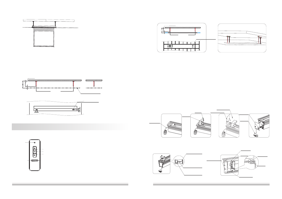
3.Please measure the security distance between hanging brackets (figure 4), and fix the hanging brackets on the
ceiling using expansion screws (figure 5).
4, Please follow the below steps to install the power cord which recessing in casing, and plug in the external infrared receiver
(because of the recessed mount, the external infrared receiver must be ready for control).
1)Take out the power cord (figure 6).
2)Loose the screws of power box and take out the power box (note: the power box must be buttoned on the hanger of bracket
according to figure 11, please put up and move back the power box to take out), because the power cord has a limit, please do
not draw it strongly.
3)Loose and take out two rubber screws, then remove the end cap (figure 8-9).
4)Remove the line cover of end cap, then fill in the power line. Afterward, stuck the line cover back to end cap, then install the
power line outside the casing.
5)Install the end cap again (figure 10)
6)Insert the external infrared receiver to EXT IR hole (figure 10) (note: please put the completed external infrared receiver into
inside frame of screen to avoid the pressing from screen). Then install the power box back to bracket (note: ensure the power
box is buttoned on the hanger of bracket) (figure 11).
figur e 4
figur e 5
TRIG(
)
Trigger
EXT IR(
)
External
Infrared Receiver
EXT CTRL(
)
Dry
Contact/RS232
Fi gur e 10
Signal Output
Switch
M4 Screw
Note: the power box must be
buttoned on the hanger of bracket.
Bracket
Power Box
End Cap Board
Fi gur e 11
Fo ur Hangi ng
Boar ds ar e in middl e.
1
0
0
H
L
94
minus
H
100
minus
1
8
0
100
Fi gur e6
Pow er Li ne
Fi gur e7
Fi gur e8
Fi gur e9
11
Product Instruction
11. Installation Completed (figure 27).
Note: the upward instructions are only suitable for the distance H which between 200-600mm; if the distance is
greater than 600mm, please follow the steps as below:
1)Install the hanging bracket at a required position before ceiling fitment (M12 bar is not provided) (figure 28).
2)Saw an oblong groove at a completed ceiling (note: please ensure the hanging bracket must be installed in the
middle of this groove) (figure 29). The rest of steps can follow the instructions as before!
Figure27
Figure29
Figure28
Two Hanging
Boards are in middle.
L(
)
26mm
Total length of screen
minus
Not completed ceiling
H
100
minus
1
0
0
L
94
minus
1
5
8
7
9
Pow er Box
Scr ew
Rubbe r Scr ew
End Cap Boar d
Pow er Li ne
Li ne Cover
100
Button Function and Operation Instruction :
1.Press UP button to lift the screen
2.Press STOP button to stop the screen
3.Press DOWN button to lower the screen
4.Press MICRO-UP button to retract the screen in small
increments(150ms for each movement)
5.Press MICRO-DOWN button to lower the screen in small
increments (150ms for each movement)
Cautions:
1.The minimum distance between Controller and Receiver: 50cm
2.Workable within 8m in horizontal directionfrom the Receiver to the
Controller
3.Do not cover the Controller’s launching port while operation
4.Strictly banoperation in wet or high temperature environment.
5.Replacing batteries when the signal is faint or no signal.
6.Batteries for the Controller: 2 units CR2032 button cells.
LED
UP
STOP
DOWN
Micro-up
Micro-down
Model:AC127