Grandview LF-PH(Concave Perm-Fixed Series) User Manual
Page 6
4
5
Screen Installation
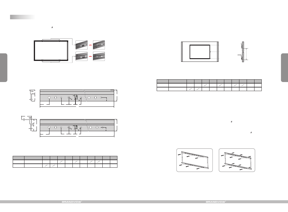
1. Each screen is equipped with 4 brackets labelled 1,2,3,4; and thus the concave frame has relevant marks of 1, 2, 3, 4.
#
#
When installing the brackets, use the 5 x10mm screws to fix the bracket 1 to mark 1 on the concave frame. Do the
#
#
#
same for bracket 2 , 3 and 4 . ( Figure 8 ). Make sure the screws are tightly fastened.
Figure 8
3
25
15
10
120
32
23
20
6
6
Lt
1
2
4
0
R
8
5
35
4
0
120
32
23
20
6
6
Lt
1
2
R
8
5
5
2
1
5
4
0
2
1
3
4:3
16:9
Lt (mm)
60"
72"
77"
80"
850
850
1000
Lt (mm)
1000
1000
92"
100"
106"
112"
120"
1150
1300
1150
1150
1300
1300
1450
150"
1600
1750
2. Each screen is equipped with a top and bottom installation bars with many sets of holes, three of which belonging to
one set. Installation bar specifications on Figure 9.
Top installation bar
Bottom installation bar
Measure unit: mm
Side view
Front view
Front view
Side view
Figure 9
Table2: Length of installation bars ( Lt )
Specification (in)
Format
Note: Sizes and specifications are subject to change at any time. Refer to real product for exact data.
3. The top and bottom installation bars have been linked in factory and the length in between is pre-set. Fix the top
installation bar at horizontal level and the bottom bar will go parallel as a result of gravity. Make sure the length in
between is conform to the table 2 .Micro adjustment is allowed. Then fix the bottom installation bar. You can also
refer to table 3 for the required distance between the installation bars. ( Figure 10-11 )
60"
72"
77"
80"
92"
100"
106"
112"
120"
Note: Sizes and specifications are subject to change at any time. Refer to real product for exact data.
1063
1101
1250
1350
1424
1499
1599
1019
1202
1324
1629
1934
150"
1972
2391
Figure 10
Figure 11
top installation bar
Bottom installation bar
Link
Distance between
installation bars
Table 3: Distance between installation bars
Specification (in)
Format
4:3
16:9
Distance (mm)
Distance (mm)
Installation details:
a. Woody wall installation: Follow the screen installation step 3 and fix the 5 x 40 mm tapping screws to the holes in the
top and down installation bars, three screws on each bar. ( Figure 12 )
b. Concrete wall installation: Follow the screen installation step 3 and drill six proper holes through the concrete wall
with electrical drill, and then nail the screw anchors into the done holes on the wall. Fix the 5 x 40 mm tapping screws
to the holes on the wall through the holes in the top and bottom installation bars, three sets of screws on each bar.
( Figure 13 )
Figure 12
Figure 13