14 replacement of parts – Glow-worm Ultrapower sxi User Manual
Page 50
50
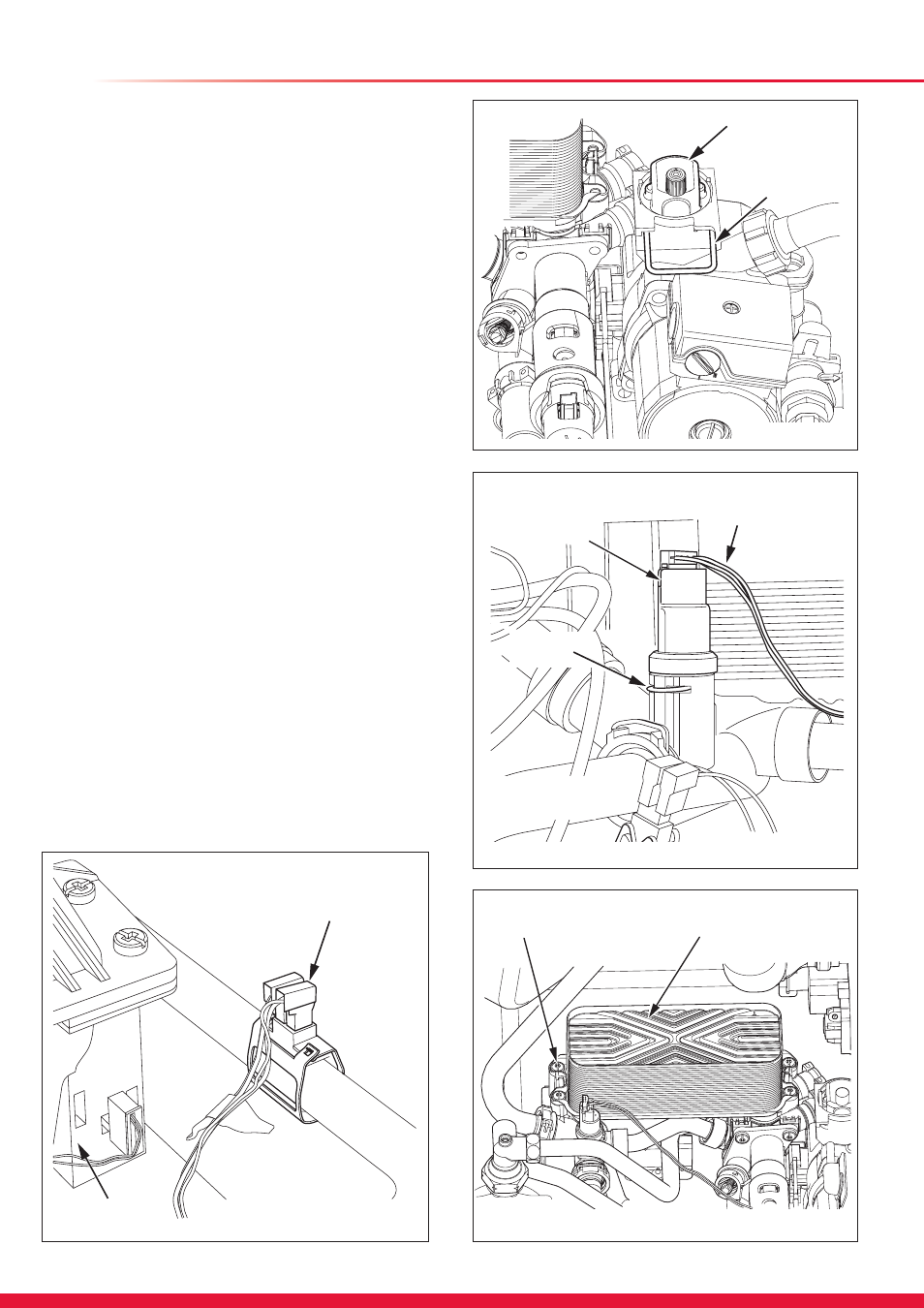
Diagram 14.17
14 Replacement of Parts
AUTOMATIC
AIR VENT
RETAINING
CLIP
13304
RETAINING
CLIP
LOW WATER
PRESSURE
SENSOR
ELECTRICAL
LEADS
LH
HYDROBLOCK
Diagram 14.19
13315
HEATING
RETURN
THERMISTOR
FAN
13310
14.23 Water Pressure Sensor
For access, refer to section 14.1.
Refer to section 14.1 and drain the boiler heating circuit.
Refer to diagram 14.19.
Disconnect the electrical lead and withdraw the lead plug.
Remove the retaining clip to remove the low water pressure
sensor.
Fit new ‘O’ ring.
14.24 Plate-to-Plate Heat Exchanger
For access, refer to section 14.1.
Refer to section 14.1 to drain the boiler heating circuit.
Refer to section 14.1 and drain the boiler domestic water
circuit.
Refer to diagram 14.20.
Remove the four screws securing the plate-to-plate heat
exchanger to the hydroblock.
There will still be water present so carefully pull the plate-to-
plate heat exchanger upwards to remove.
When replacing the plate-to-plate heat exchanger ensure that
the four rubber seals are fitted into the hydroblock.
NOTE: The plate-to-plate heat exchanger only fits one way.
Open the cold-water isolation valve and slowly open a hot
water tap to remove air.
Close the hot water tap and check for any leaks.
Open the heating circuit isolation valves, re-pressurise the
system as necessary.
Diagram 14.20
PLATE TO PLATE
HEAT EXCHANGER
SECURING
SCREWS (4)
13348
Diagram 14.18