12 servicing – Glow-worm Ultrapower sxi User Manual
Page 33
33
12 Servicing
Diagram 12.4
13344
CONTROL BOX IN SERVICE POSITION
DOMESTIC
EXPANSION
VESSEL
SERVICE SUPPORT
BRACKET
SERVICE POSITION
FILLING
LOOP
13329
13330
DOMESTIC
EXPANSION VESSEL
FLEXIBLE
HOSE
BRACKET
UNION NUT
(Do not loosen)
LOCK NUT
SECURING
SCREW
HEAT
EXCHANGER
SILENCER
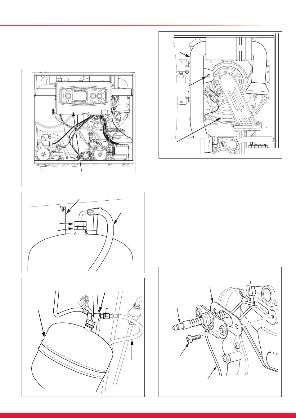
12.2 Silencer
For access to the heat exchanger the silencer will need to be
removed, see diagram 12.7.
Remove the securing screw and pull the silencer from the gas
valve, this is a push fit.
13343
ELECTRODE
GASKET
SPARK GAP
4mm
SECURING
SCREW
(2 OFF)
EARTH
LEAD
13273
Diagram 12.8
Diagram 12.7
Diagram 12.5
Diagram 12.6
12.3 Spark Electrode
NOTE:
If the functional checks did not indicate poor
combustion then it is not necessary to service this
component.
Disconnect the spark electrode plug and earth lead. Remove
the two securing screws and withdraw the spark electrode
carefully from the combustion chamber, see diagrams 12.8
and 12.9.
Inspect the tips for damage.
Clean away any debris and check the spark gap is 3.5 to
4.5mm.
Check the electrode gasket for signs of damage and replace if
necessary.
NOTE: If the burner is not to be serviced, do not perform the
following instructions 12.6, 12.7, 12.8 and 12.9 but continue to
section 12.10 to complete the servicing.