14 replacement of parts – Glow-worm Ultrapower sxi User Manual
Page 46
46
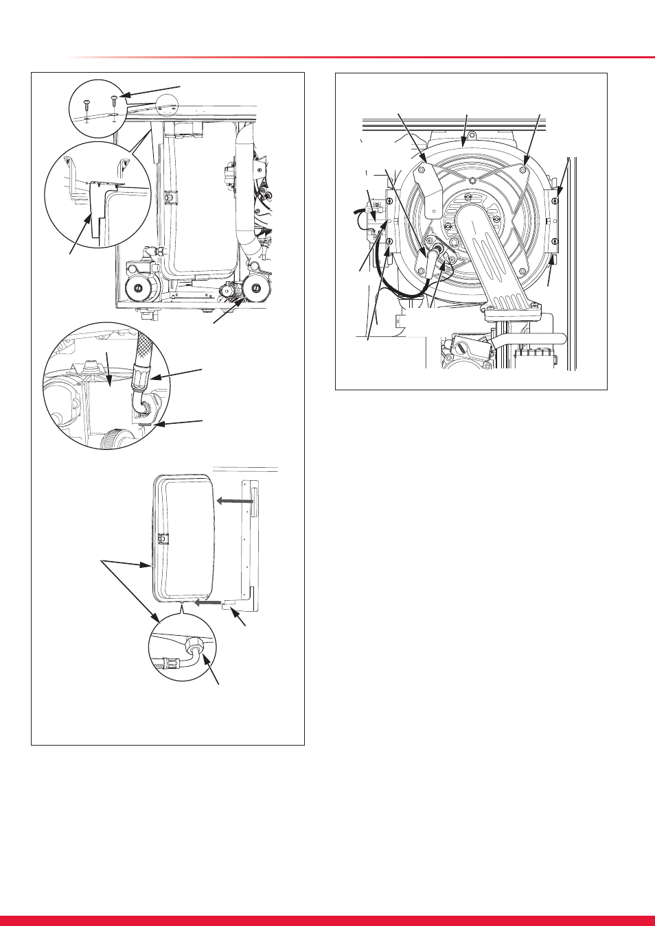
14.13 Heating Expansion Vessel
For access, refer to section 14.1.
Drain the boiler heating circuit, refer to section 14.1.
Remove the retaining clip from the flexible hose at the central
heating pump, see diagram 14.7.
Remove the flexible hose from the pump, ensure the ‘O’ ring
on the connection is seated correctly before re-fitting.
Remove the expansion vessel clamp, see diagram 14.7.
Slide the expansion vessel forward and out from the retaining
bracket.
Remove the flexible hose union nut from the expansion
vessel. When re-fitting ensure that a new sealing washer
is fitted and that the elbow of the flexible connection faces
towards the front of the appliance.
14.14 Heat Exchanger
Refer to Manual Handling Operations, 1992.
For access, refer to section 14.1.
Drain the boiler heating circuit, see section 14.1.
Drain the boiler domestic water circuit, see section 14.1.
Disconnect the flue connection.
Remove the silencer, refer to section 12.2.
Remove the igniter unit electrical connections, refer to
diagram 14.2.
Refer to section 12.4 for removal of the fan, gas valve and
burner assembly.
14 Replacement of Parts
Diagram 14.7
13354
Diagram 14.8
SILENCER
BRACKET
EARTH
LEAD
IGNITION
LEAD
HEAT
EXCHANGER
SECURING
NUT (4 OFF)
SECURING
SCREW
(2 OFF)
CLAMP
SECURING
SCREW (2 OFF)
CLAMP
IGNITER
UNIT
13351
RETAINING
BRACKET
PRIMARY
EXPANSION
VESSEL
FLEXIBLE HOSE
CONNECTION
SECURING
SCREW (2 OFF)
EXPANSION
VESSEL
CLAMP
RETAINING
CLIP
Top view of CH pump
CH PUMP
FLEXIBLE HOSE
CONNECTION
CH PUMP