1 general – Glow-worm Inset BBU50 User Manual
Page 5
5
221723B
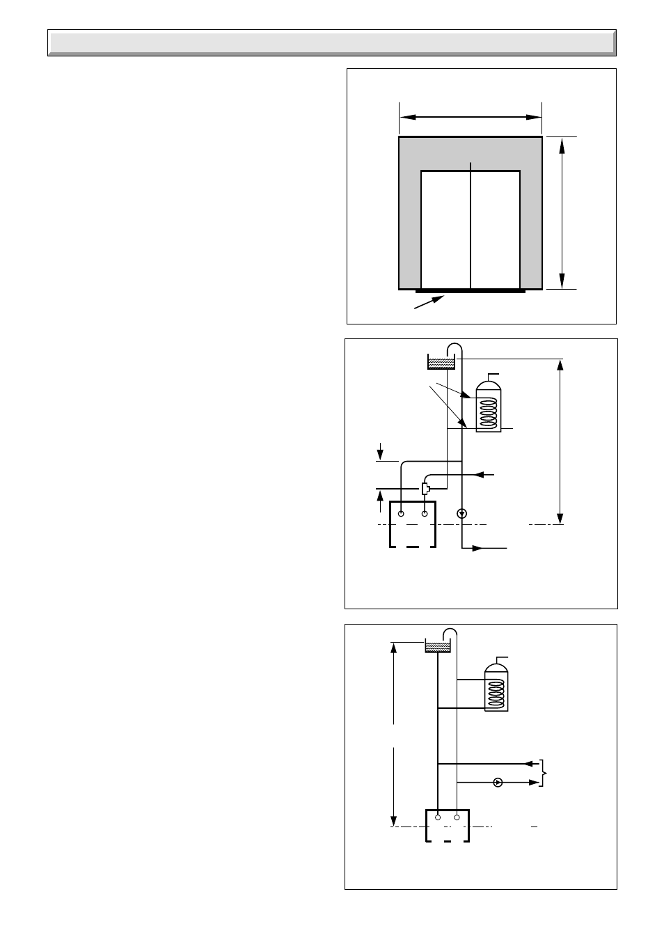
Diagram 1.4
Diagram 1.5
6242
6243
BOILER
22mm
CENTRAL
HEATING
RETURN
28mm
DISTRIBUTOR
TUBE IN RETURN
CONNECTION
22mm
CENTRAL
HEATING
FLOW
FLOW
RETURN
INDIRECT
CYLINDER
27 METRES
MAXIMUM
FIXED
DIMENSION
C
L
INDIRECT
CYLINDER
PUMP
TO HEATING
CIRCUIT
1 METRE MIN
27 METRE MAX
RETURN
FLO
W
BOILER
C
L
PUMPED HEATING & GRAVITY DOMESTIC HOT
WATER (DIAGRAMMATIC)
FULLY PUMPED SYSTEM
(DIAGRAMMATIC)
1.5 Contents of Packaging
The boiler is delivered in one pack which contains all the parts
required for installation.
1.6 Site Requirements
For all types of installation a standard 16inch builder’s opening
is required, see diagram 1.2.
Note: The depth of the fire opening is IMPORTANT, it MUST
therefore conform to the dimensions given in diagram 1.2.
Any larger opening will need to be reduced, with non-combustible
material to conform to this requirement.
It is important that the opening is cleared of debris and mortar
etc.
The prepared base for the back boiler must be level.
Refer to diagram 1.3 for dimensions of the fire fixing wall face
which MUST be true.
1.7 Water System - Open Vented
This boiler can be used on an unrestricted open vented system
with the water supply taken from a feed and expansion cistern,
having a head between 1m (3ft 3in) minimum and 27m (90ft)
maximum.
Diagrammatic layouts of systems are shown in diagram 1.4 and
1.5.
Sealed Water System
A Kit and instructions, Part No. 459033, is available to enable
the back boiler to be used on a sealed water system.
Please give the serial number of the back boiler unit when
ordering the kit.
1.8 Hot Water Cylinder
The back boiler is suitable for open vented systems using an
indirect cylinder (including single feed self priming type). The
cylinder must be fitted to the manufacturer’s recommendations
and the system must conform to the requirements of the current
issue of BS5449.
It is recommended that the cylinder be fitted with some form of
temperature control.
1.9 Frost Protection
If the position of the boiler is such that it may be vulnerable to
freezing it should be protected as specified in the current issue
of BS5422.
It is also recommended that a frost thermostat is fitted.
1.10 Draining Tap
A draining tap must be provided at the lowest point of the system
which will allow the entire system, the boiler and hot water
cylinder to be drained.
Draining taps shall be to the current issue of BS2879.
1.11 Safety Valve
A safety valve need not be fitted to an open vented system.
1.12 Boiler Location
This back boiler unit MUST NOT be installed in a private garage
or in a room containing a bath or shower or a room used or
intended to be used as sleeping accommodation.
1 General
Diagram 1.3
C
L
5506
690
Minimum flat area and fixture or
surround protection clearance
PREPARED BASE
800 MIN WIDE FRAME
780 MIN STANDARD FRAME