9 fault finding – Glow-worm Inset BBU50 User Manual
Page 22
22
221723B
9 Fault Finding
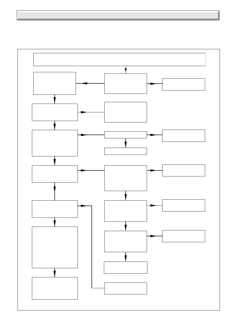
Diagram 9.1
ELECTRICAL FAULT-FINDING BACK BOILER
7428
9.1 Electrical
Carry out the preliminary electrical system checks as contained
in a multimeter instruction book.
Refer to electrical fault finding chart, diagram 9.1 and functional
flow wiring diagram 9.2.
On completion of the fault finding task which has required the
breaking and remaking of electrical connections, the checks for
earth continuity, short circuit, polarity and resistance to earth
must be repeated.
Ensure all connections are correctly made, that gas supply is available free of obstruction
and purged of air. Ensure that external controls, if fitted, are calling for heat.
YES
YES
Does sparking take
place, does milli-voltage
increase towards 5mV?
Pilot not lit.
Check condition of
electrode and HT lead.
Replace as necessary.
30 seconds after
a call for heat, is there
230V ac on
L and N CN6
NO
Is milli-voltage > 5mV?
Faulty PCB. Replace.
NO
Faulty thermocouple.
Replace.
Faulty gas control valve.
Replace.
Appliance working
satisfactorily.
NO
Faulty PCB.
Replace.
NO
YES
Does green light on
lockout reset button
illuminate and sparking
stop when milli-voltage
is >5mV?
YES
Is there 230V at
both connections on
the thermostat control
with reference
to neutral?
Is there 230V at
PIN EV2 on CN3 on
PCB with reference
to neutral?
YES
Check continuity of
lead from PCB to
gas control valve,
is there continuity?
YES
NO
NO
Faulty thermostat
control. Replace.
NO
Faulty PCB.
Replace.
NO
Faulty lead.
Replace.
NO
YES
The flue blockage
safety device
has operated, the main
burner has gone out.
Check adequate
ventilation is available,
check flue has not
become blocked.
YES
Turn control thermostat
knob to maximum.
Does main burner light?
YES
Does red light on
lockout reset button
illuminate?
Press lockout reset
button. Ignition should
take place, appliance
should work satisfactorily.
Connect a multimeter
set to mVDC to pins
TC-GND and TC-SGN
on CN1 on the PCB
START