4 installation – Glow-worm Inset BBU50 User Manual
Page 11
11
221723B
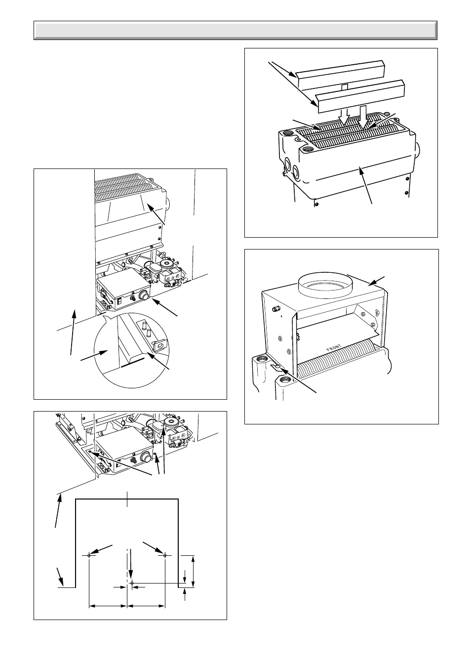
Diagram 4.8
8060
DRAUGHT
DIVERTER
SECURING SCREWS (2)
Pipework removed for clarity
(Left hand water connection shown)
4 Installation
Reposition the back boiler unit into the builder’s opening.
Connect the system pipework to the back boiler unit/pre-
plumbed pipework.
Connect gas supply to gas service cock. Leave gas service
cock and gas fire front cock in the “OFF” position, see diagram
4.11 and 6.2.
If a flexible flue liner is being used, position the liner in to the flue
socket. Using two No8x
1
/
2
in self tapping screws, coloured
black, from the fittings pack, screw through the two remaining
holes in the flue socket to centralise and secure the flue liner,
see diagram 4.10. Seal with a suitable fire clay cement.
Diagram 4.5
6179
NOTCH
BASE
FIXING
WALL
FACE
HEAT
EXCHANGER
CASTING
C
L
150
13
12.5
150
126.5
Diagram 4.6
6204
FIXING
HOLES
FIRE
FIXING
WALL
FACE
TOP VIEW INSIDE
BUILDERS OPENING
FIXING
HOLES
Diagram 4.7
7980
BAFFLES (centre in flueway)
HEAT EXCHANGER
BACK
FLUEWAY
MIDDLE
FLUEWAY
Pipework removed for clarity
(Left hand water connection shown)
- 12-38hxi Range (44 pages)
- 18-30sxi Range (48 pages)
- 23c (44 pages)
- 24-38CXI Range (52 pages)
- 30ci Plus (56 pages)
- BBU 45/4 (32 pages)
- BBU 54/4 (32 pages)
- Betacom C (68 pages)
- Betacom2 (8 pages)
- Betacom2 (20 pages)
- Betacom2 (56 pages)
- Black Beauty 4 (20 pages)
- Chatsworth 4 (24 pages)
- Clearly Heat Recovery (20 pages)
- Clearly Heat Recovery (32 pages)
- Clearly Heat Pumps Envirosorb3 (28 pages)
- Clearly Heat Pumps Envirosorb2 (44 pages)
- Clearly Heat Pumps 7kW (44 pages)
- Clearly Heat Pumps 5kW (28 pages)
- Clearly Heat Pump 5kW (16 pages)
- Clearly Heat Pump 5 kW (32 pages)
- Clearly Heat Pump - Buffer Vessel (10 pages)
- Clearly Heat Pumps - Standalone Module System (40 pages)
- Clearly Heat Pumps - Standalone System (28 pages)
- Clearly Hybrid - Universal Module (20 pages)
- Clearly Hybrid - Universal Module System (36 pages)
- Clearly Hybrid - Compact Hydraulic Module (12 pages)
- Clearly Hybrid - Compact System (36 pages)
- Clearly Hybrid - Compact Hydraulic Module HB (16 pages)
- Clearly Hybrid - Back-up Module System (40 pages)
- Clearly Solar System Hydraulics (28 pages)
- Clearly Solar System (28 pages)
- Clearly Solar Controller (28 pages)
- Clearly Solar Horizontal On-Roof Collector (16 pages)
- Clearly Solar Vertical On-Roof Collector (16 pages)
- Clearly Solar Cylinders (32 pages)
- Clearly Solar - A-Frame (28 pages)
- Clearly Solar Horizontal In-Roof Collector (32 pages)
- Clearly Solar Vertical In-Roof Collector (44 pages)
- Clearly Solar Collector Container (8 pages)
- Climapro 1 (12 pages)
- Climapro2 RF (16 pages)
- Climapro2 RF (24 pages)
- Climapro2 RF (36 pages)
- Climapro2 RF (32 pages)