4 installation – Glow-worm Hideaway 80CFF User Manual
Page 13
13
2000225006B
4.6 Side Casings
Fit the side casings by locating their lugs into the appropriate
slot in the boiler plinth, see diagram 4.7, depending on the
required height, there are two options, see section 1.7.
Secure the casing sides to the front and rear upper casing
brackets with self-tapping screws supplied, see diagrams 4.7
and 4.8.
Note: If the side in-fill panels are being fitted they should be fitted
at the same time as the side casing, see next section.
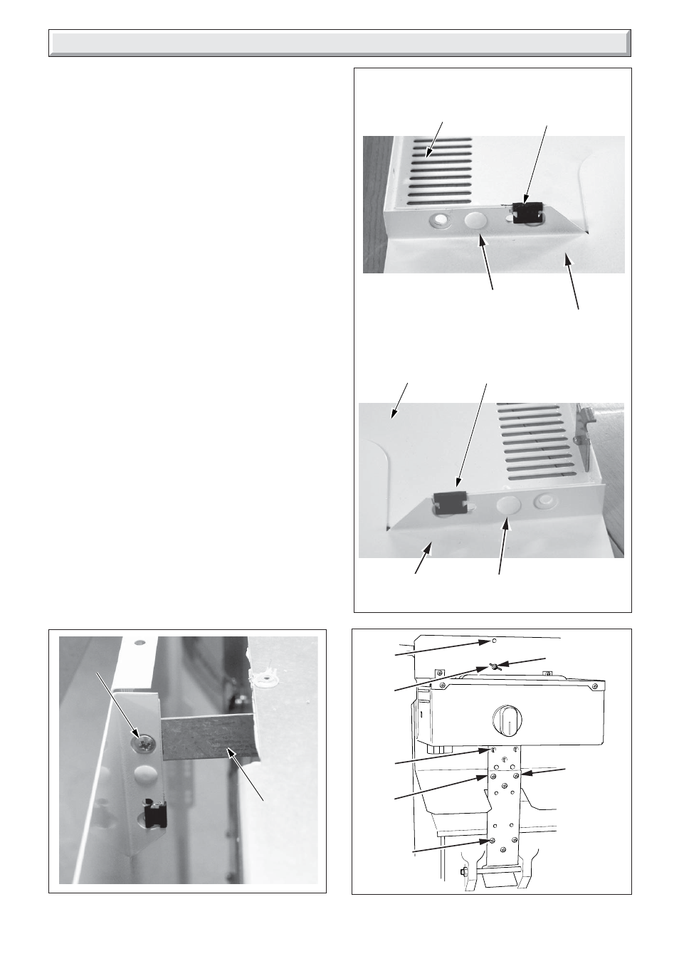
4.7 Side In-fill Panel (if required)
The side in-fill panel is supplied with the boiler, which can be
fitted at the rear of the left and right hand side casing but can be
discarded if the water connections are made on both sides of
the boiler or if the boiler is screened by fixtures. The in-fill panel
will usually be fitted on the side where there are no pipework
connections.
Insert the push fit plastic location peg, supplied, through the in-
fill panel and side casing holes and secure with the spring clips,
see diagram 4.9.
NOTE
The boiler is assembled at the factory with the control box and
heat shield fitted in the lower casing height position.
4 Installation
Diagram 4.10
0886
WING NUT
SELF
TAPPING
SCREWS
(3)
(3) SELF
TAPPING
SCREWS
(for height
adjustment
only)
"LOW"
position
"HIGH"
position
"LOW"
position
"HIGH"
position
Diagram 4.9
PLASTIC
PEG
PLASTIC
PEG
SPRING
CLIP
SIDE
CASING
(R.H.SHOWN)
UPPER VIEW
LOWER VIEW
SPRING
CLIP
SIDE
CASING
(R.H. SHOWN)
IN-FILL
PANEL
IN-FILL
PANEL
Diagram 4.8
SCREW
UPPER
CASING
BRACKET
SIDE CASING
(R.H. SHOWN)