1 general – Glow-worm 45/2 Back Boiler User Manual
Page 3
3
221780A
1 General
RANGE RATING
NOMINAL
kW
HEAT INPUT
(GROSS)
Btu/h
NOMINAL
kW
HEAT
OUTPUT
Btu/h
BURNER
mbar
SETTING
PRESSURE
in.w.g
12.9
15.4
17.8
44,100
52,500
60,900
3.3 FF2022
9.5
11.7
13.7
32,450
39,800
46,750
8
11.4
15.2
3.21
4.54
6.10
INJECTOR
MARKING
Minimum Medium
Maximum
RANGE RATING TABLE
1.2 Data
Gas connection
Rc
1
/
2
(
1
/
2
inBSPT)
Water connection
Rc1 (1inBSPT)
Electrical supply
230V~50Hz fused 3A
Weight, about
42.5kg (93.7lb)
Water content
5.6Litres (1.23gall)
Injector
3.3mm
Dimensions are given in millimetres (except as noted).
Data Label: Bottom left of control tray.
1.3 Gas Supply
The gas installation shall be in accordance with the current issue
of BS6891.
The supply from the governed meter must be of adequate size
to provide a steady inlet working pressure of 20mbar (8in wg) at
the back boiler.
On completion test the gas installation using the pressure drop
method and suitable leak detection fluid, purge in accordance
with the current issue of BS6891.
1.4 Electrical Supply
WARNING. This back boiler must be earthed.
All system components shall be of an approved type and shall
be connected in accordance with the current issue of BS7671
and any applicable local regulations.
Connection of the back boiler and system controls to the mains
supply should be through a double pole isolating switch, fused
3A having a minimum contact separation of 3mm in both poles.
Alternatively, a fused 3A 3 pin plug and unswitched socket outlet
to the current issue of BS1363 may be used.
Wiring to the back boiler must be PVC (85
o
C) insulated type to
the current issue of BS6500 Table 16, not less than 0.75mm
2
(24/0.20mm).
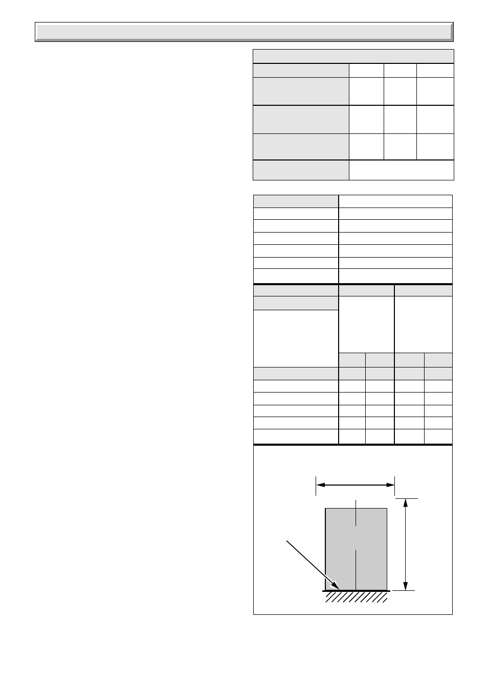
1.5 Site Requirements
Refer to diagram 1.1 for dimensions appropriate to the back
boiler.
For all types of installation a standard sized builder’s opening is
required, see diagram 1.2.
It is important that the opening is cleared of debris and mortar.
It is recommended that the access hole for pipework into the
fireplace or builder’s opening is either at the left hand or right
hand side of the chimney breast. If access is required at both
sides then it may be necessary to prepare some of the
connections before fitting the back boiler into the builder’s
opening.
The prepared base for the back boiler must be level.
Refer to Table 2 for dimensions of fire front fixing wall face which
must be true.
1.6 Water System - Open Vented
This back boiler can be used on an unrestricted open vented
system with the water supply taken from a feed and expansion
cistern, having a head between 1m (3ft3in) minimum and 27m
(90ft) maximum.
Diagrammatic layouts of systems are shown in diagram 1.3 and
1.4.
Dimensions
for
minimum
flat area
(no fixtures)
Dimensions
for fixture or
surround
protection
clearance
3013
FRONT
OPENING
CL
ALL DIMENSIONS IN MM
PREPARED
BASE
Y
X
G.C No.
Teak
Mahogany
T a b l e 1
FIRE TYPE
Miami 3 BBU
37-047-04A 37-047-07A
Melody 3 BBU
37-047-06A
Black Ash 3
37-047-08
Saxony 3
37-047-09
Brown Ember 3
37-047-02
T a b l e 2
FIRE
TYPE
X
Y
X
Y
Miami 3 BBU
642
698
750
836
Melody 3 BBU
642
698
750
836
Black Ash 3
700
660
840
890
Brown Ember 3
795
707
905
892
Saxony 3
700
625
840
860