8 servicing, 9 replacement of parts – Glow-worm 45/2 Back Boiler User Manual
Page 17
17
221780A
5079
8 Servicing
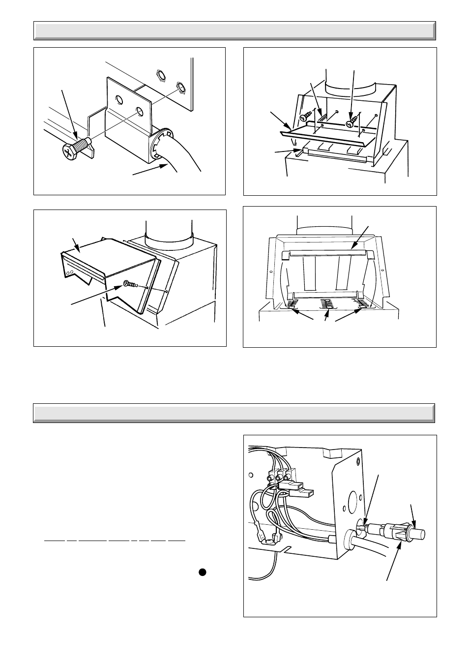
Diagram 8.9
Diagram 8.8
Diagram 8.6
Diagram 8.7
5201
1620
6048
FLUE
BAFFLE
FLUE COLLECTOR
ASSEMBLY
SECURING
SCREW
STAINLESS STEEL
SECURING SCREWS(2)
GUIDE
CHANNELS
FLUE
BAFFLE
DIVERTER
PLATE
FIRE FRONT
SENSING TUBE
SECURING
SCREW (2)
FLUEWAY
BAFFLES
9.1 Notes on Replacing Parts.
(a) Replacement of parts must be carried out by a competent
person.
(b) Unless stated otherwise all parts are replaced in the reverse
order to that of removal.
(c) After replacing any gas carrying parts always test for gas
soundness using a suitable leak detection fluid. Also carryout
functional check of controls.
(d) Refer to the Gas Fire Front Installation Instructions for
details of the removal of the fire front.
(e) Isolate the electrical supply to the back boiler.
(f) Remove the gas fire front plinth.
(g) Refer to diagram 6.1 to identify the back boiler controls.
Turn the gas valve control knob “A” clockwise to
“Off”
position. Turn the appliance gas service cock anticlockwise to
“Off” position, see diagram 6.2.
9 Replacement of Parts
Diagram 9.1
RETAINING
TABS
IGNITION LEAD
(BLACK END)
PIEZO
UNIT
8033