10 fault finding – Glow-worm 45/2 Back Boiler User Manual
Page 20
20
221780A
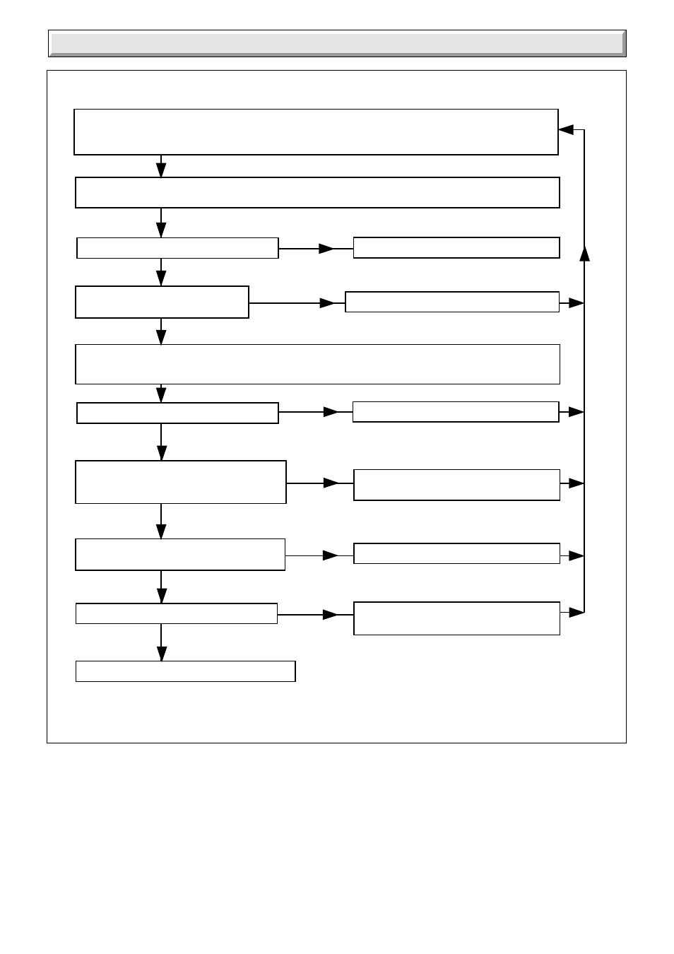
ELECTRICAL FAULT FINDING CHART
4484A
Diagram 10.2
Isolate power supply to the control box. Gain access to the control box and physically check all wires and
connections. Check fuses.
Check that all remote controls, (eg room and / or cylinder thermostats), are making contact for duty.
Turn on the power supply to the control box. Turn on the boiler thermostat and measure the voltage
between C and N.
Is the voltage between 216 and 264 volts.
Check control box wiring and mains supply
Isolate the power supply. Replace thermostat
Is there voltage between NC and N.
216 and 264 volts.
Isolate the power supply to the control box. Remove plug from gas valve and connect
voltmeter between L and N in plug, ensuring no short circuits (mains voltage). Turn on power supply and
measure voltage.
Is the voltage between 216 and 264 volts.
Check control box wiring.
Isolate the power supply to the control box.
Reconnect gas valve. Turn on
power supply. Does main burner light.
Turn off boiler thermostat, measure voltage
across 3 and 4. Is the voltage zero.
Does the main burner extinguish.
Boiler electrical system operating satisfactorily
Isolate power supply.
Replace gas valve.
Isolate power supply. Replace thermostat.
Isolate power supply.
Replace gas valve.
YES
NO
NO
YES
NO
YES
YES
YES
YES
NO
NO
NO
Isolate power supply to the control box. Gain access to the control box and physically check all wires and
connections. Check fuses. Check Flue Blockage Safety Device filter is not blocked, clear if necessary.
Check that all remote controls, (eg room and / or cylinder thermostats), are making contact for duty.
10 Fault Finding