12 servicing, Attention! 12. 6 combustion check – Glow-worm cxi and Gas Valve User Manual
Page 34
34
0020013349-02
Diagram 12.8
9183
DOMESTIC
COLD WATER
INLET FILTER
HOUSING
SECURING
CLIP
PUMP
12 Servicing
If a gas carrying component has been replaced, the combustion
of the appliance should be checked as follows. Once the
appliance has been re-assembled (apart from the front and
inner casing panels) connect a CO
2
combustion analyser to the
test
point on the flue adapter, see diagram 12.1.
Turn on the gas service cock, see diagram 7.1.
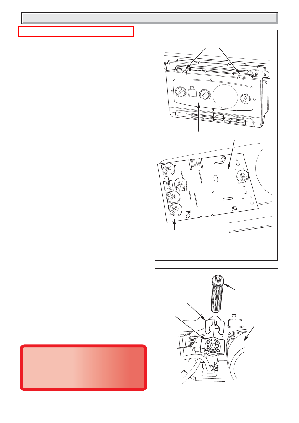
With the power off and the appliance cold, unclip the controls
fascia and hinge it down to reveal the potentiometers on the rear
of the User interface, see diagram 12.7. Take care not to allow
the fascia to drop down and damage the wiring.
Turn on the electrical supply.
Ensure external controls are calling for heat. The boiler should
fire automatically.
Allow the boiler to fire for a minimum of 60 seconds and then,
using an electrical screwdriver, rotate the service potentiometer
fully clockwise, see diagram 12.7. This will allow the digital
display to indicate the 'flashing' fan speed on the appliance
fascia.
In the fully clockwise position the display should be indicating
the maximum fan speed of the appliance, in central heating
mode this should be 39±1 for 24cxi, 45±1 for 30cxi and 45±1 for
38cxi. With domestic hot water max. demand this should be
51±1 for 24cxi, 57±1 for 30cxi and 57±1 for 38cxi. Check the
CO
2
value, which should be 9.1% +0.2 -0.5.
Note that with the inner casing panel fitted the combustion
readings will increase slightly to 9.3% +0.3 -0.5.
If adjustment proves necessary then proceed as follows.
Any adjustment to the gas valve should only be carried out by
a competent person.
Refer to diagram 11.4.
Adjust the maximum rate CO
2
with the throttle to 9.1%. (Rotate
anti-clockwise to increase).
Rotate the service potentiometer fully anti-clockwise. Hold it in
this position for about 5 seconds before rotating the service
potentiometer clockwise to the mid-point or 3 o'clock position.
The fan should reduce to 1200 ± 100 rpm which will flash '12' ±1
on the digital display.
Check the CO
2
value, which should be 9.1% +0.2 -0.5.
For Propane the CO
2
value, should be 10.5% +0.3 -0.7.
If adjustment proves necessary then proceed as follows.
Adjustment of the CO
2
at minimum rate is very coarse so
carefully adjust the CO
2
with the offset adjustment to 9.1%, see
diagram 11.4.
Rotate the service potentiometer fully clockwise, see diagram
12.7 and re-check the maximum rate combustion, which should
be 9.1% +0.2 -0.5.
After checking combustion rotate the service potentiometer
fully anti-clockwise so that the display indicates the water
temperature.
Replace the cap on the test point and refit the control cover rear
panel.
Diagram 12.7
MIN.
MAX.
POTENTIOMETERS
RETAINING
LATCHES
SERVICE
POTENTIOMETER
11472
11417
CONTROLS
FASCIA
USER INTERFACE