5 domestic hot water system, 6 installation preparation – Glow-worm cxi and Gas Valve User Manual
Page 18
18
0020013349-02
6.1 Appliance Pack
IMPORTANT: With regards to the Health and Safety Manual
Handling requirements, two persons shall be required to lift the
appliance, refer to Manual Handling section on page 5.
Please check the boiler contents as shown in diagrams 6.1 and
6.1a.
NOTE: The fittings pack, pipe pack and document pack are
located in the polystyrene packing on the top of the boiler.The
flexible condensate outlet pipe is located in the base polystyrene
packing under the boiler base.
Remove the polystyrene end packing pieces then carefully lay
the boiler on its back, remove the two front casing panel
securing screws and lift off the panel from two retaining lugs.
Remove the transit packaging behind the front panel and
discard.
Carefully place front panel and screws to one side.
Diagram 6.1
12756
5.1 Water Pressure
The maximum working pressure of the domestic hot water
circuit is 10 bar. If the cold water supply pressure exceeds this,
then a pressure-reducing valve must be fitted in the supply to
the boiler.
5.2 'Hard' Water Areas
The temperatures within the heat exchanger are limited by the
boiler control system to minimise scale formation within the hot
5 Domestic Hot Water System
water pipework. However, in areas where the water is 'hard' (i.e.
more than 200mg/litre), it is recommended that the hot water
setting is reduced and that a scale reducer is fitted.
Refer to the manufacturer's instructions or consult the local
water company for additional advice.
5.3 Domestic Water Flow Rate
The water flow rate is restricted to a maximum 8 l/min (24cxi)
12 l/min (30cxi) and15.5 l/min (38cxi) by a restrictor fitted during
boiler installation, see diagram 7.1.
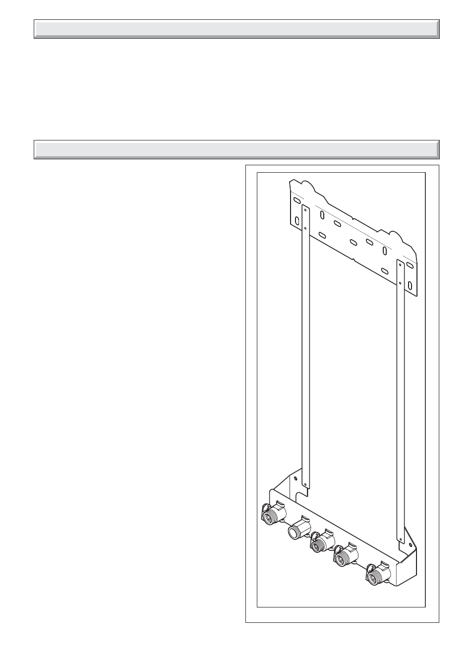
6 Installation Preparation
FIXING JIG