1 installation, 2 site requirements, 3 clearances – Glow-worm Clearly Heat Pump - Buffer Vessel User Manual
Page 7: 4 unpacking and installing the unit, Series connection parallel connection, 60 litre
7
1.2 Site requirements
IMPORTANT: To prevent frost damage to the buffer vessel
and damage caused by escaping water, do not install the
vessel in rooms that are liable to freezing.
Make sure that the floor is level and strong enough to support
the weight of the buffer vessel in its full condition (see Section
2, Technical Data).
Install the buffer vessel as close as possible to the heat pump,
to minimise heat losses. Choose the installation location so
that running and connecting the pipes is practicable. Lag all
the pipes with thermal insulation to prevent energy losses.
1.3 Clearances
When installing, make sure there is adequate clearance to the
walls, so that assembly and maintenance work can be carried
out.
1.4 Unpacking and installing the unit
The Glow-worm buffer vessel is delivered in a packing case
with a separate mini pallet for ease of handling.
The feet of the buffer vessel are secured to the pallet during
transit.
Remove the bolts from the feet of the vessel and discard.
Transport the buffer vessel to its final installation location.
Position the buffer vessel, always ensuring good access to
the hydraulic connections.
15506
15507
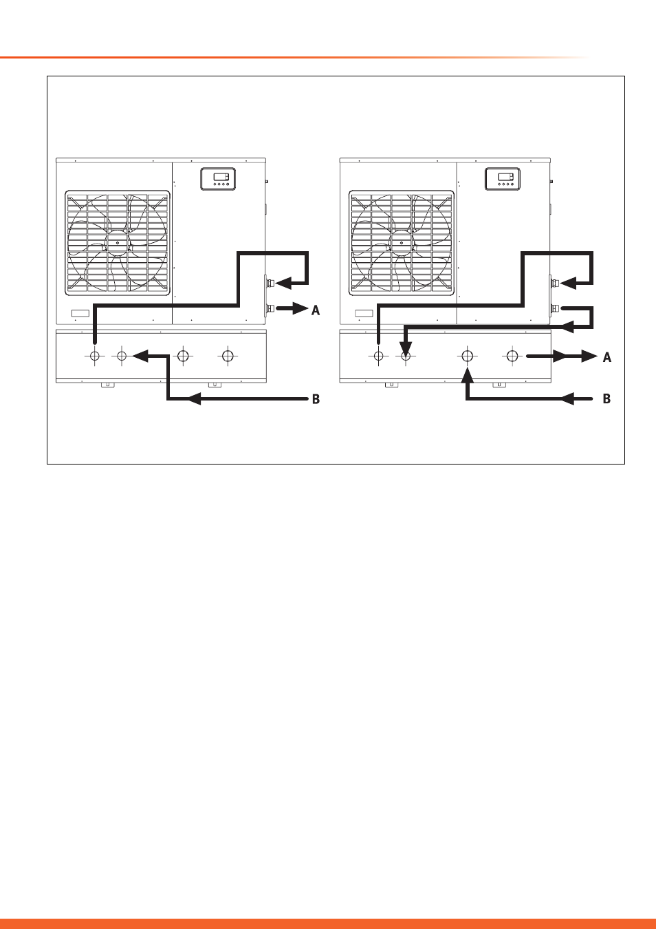
Diagram 1.2
Series connection
Parallel connection
A = to heating installation
B = from heating installation
A = to heating installation
B = from heating installation
1 Installation
60 Litre