2 ethernet port, And one to indicate ethernet activity – Digi RCM4000 User Manual
Page 37
User’s Manual
31
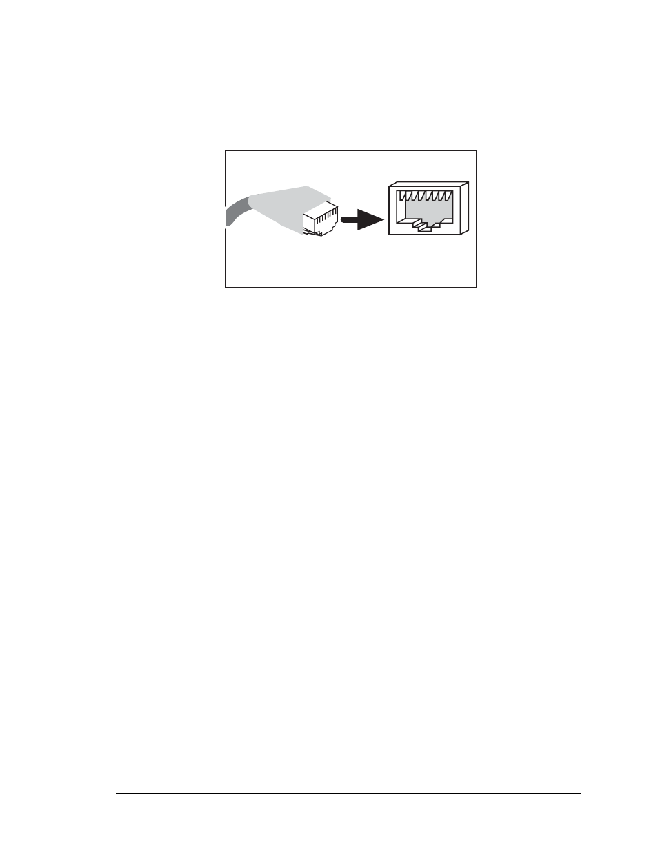
4.2.2 Ethernet Port
Figure 8 shows the pinout for the RJ-45 Ethernet port (J2). Note that some Ethernet con-
nectors are numbered in reverse to the order used here.
Figure 8. RJ-45 Ethernet Port Pinout
Two LEDs are placed next to the RJ-45 Ethernet jack, one to indicate an Ethernet link
(
LINK
) and one to indicate Ethernet activity (
ACT
).
The RJ-45 connector is shielded to minimize EMI effects to/from the Ethernet signals.
ETHERNET
RJ-45 Plug
1. E_Tx+
2. E_Tx
3. E_Rx+
6. E_Rx
1
8
RJ-45 Jack