0 installation, Figure 2: interior view – ENMET GS-24-DF Gas Sampler User Manual
Page 7
3
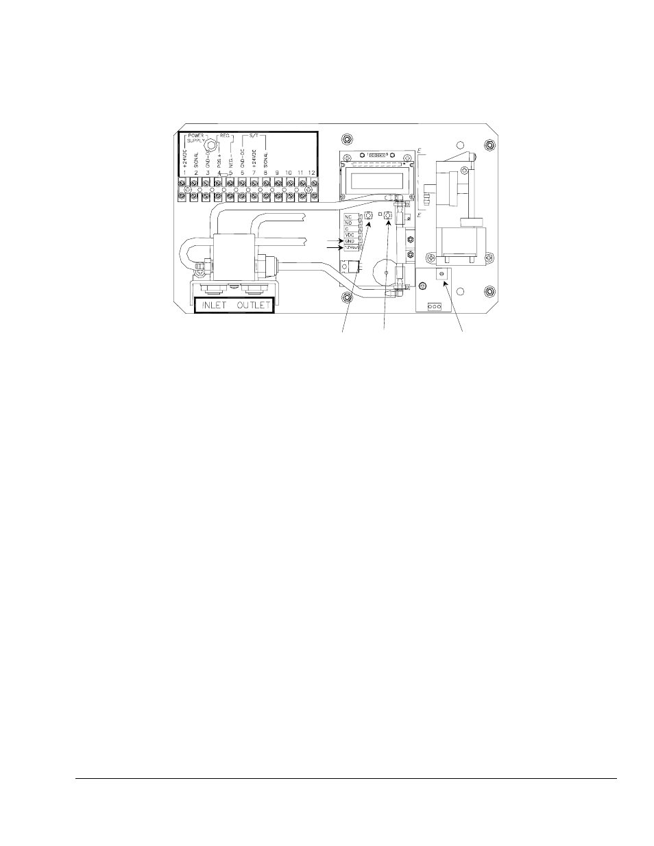
Figure 2: Interior View
3.0 Installation
The GS-24-DF needs to be level and as close to the area to be monitored as possible, to reduce transport time to
the sensor/transmitter.
• Sensor/Transmitters can be located within the GS-24-DF or remotely.
• Inlet tubing must be compatible with the target gas.
Non reactive gases Standard vinyl or tygon tubing, ENMET part number 73073-001
Reactive gases
Teflon lined vinyl or tygon tubing, ENMET part number 73073-029
• Caution should be used to insure that fluids do not enter the inlet tubing.
• Some types of gases require that the sample gas be removed from the area.
This is accomplished with the outlet port.
• Power is supplied from an external source.
Connect 24 V
DC
to terminal block positions 1 and 3.
• Note 12Vdc output is available on the pump module.
• After installing all the tubing and the sensor/transmitter, verify that there are no leaks in the system.
Verification should be done by plugging the inlet tube.
If the system is correct the flow meter reads zero and the flow alarm activates.
If this does not happen, check all fittings and seals.
Display
Pump
Gas
Sensing
Chamber
SW1
M
ENU
Switch
SW2
S
ELECT
Switch
POT
Flow Adjust
Output