0 features, Figure 1: front view – ENMET GS-24-DF Gas Sampler User Manual
Page 6
2
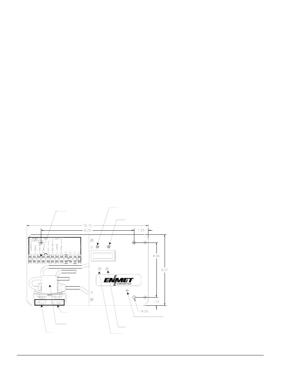
2.0 Features
See Figure 1 and 2
Feature
Description
Power Terminal
This terminal provides connections for: the DC power (24 V
DC
) supplied from external
power source, Sensor/Transmitters and 4-20mA
Display
LCD, Allows the user to verify and monitor the flow rate of the air sample. Standard flow
rate, approximately 05 lpm(liter per minute).
Indicator LED
Green/Red: When green indicates flow rate is sufficient.
When red indicates flow rate is inadequate.
Yellow: When on solid indicates GS-24-DF is in menu to change settings
When flashing indicates GS-24-DF is in menu to calibrate(factory use only)
Sampling Pump
This electromagnetic diaphragm pump draws the air sample from the test area to the sensor
chamber.
Pushbutton Switch
SW1: Menu Switch, this switch is for viewing/changing display settings.
SW2: Select Switch, this switch is for temporary deactivating audio alarm and changing
display settings.
Potentiometer
Flow Adjustment Potentiometer (POT)
Inlet Port
This port draws the air sample from the test area. For external piping, use ¼
″ O.D. tubing.
See section 4 for type of tubing to be used.
Outlet Port
This port expels the air sample after it passes the sensor. For external piping, use ¼
″ O.D.
tubing
Gas Sensing Chamber
This chamber directs the air sample to the gas sensor. Varies, depending on the type of
sensor/transmitter.
Figure 1: Front View
Flow Rate Indicator Red when in Alarm
Menu Indicator Yellow when in Menu Mode
Power Terminal
Pushbutton switch M
ENU
(SW1)
Pushbutton switch S
ELECT
(SW2)
Outlet Port
Inlet Port
Gas Sensing
Chamber
Potentiometer for
Flow Adjustment