ENMET ISA-44-RALE-OD User Manual
Page 25
ISA-44RALE-OD/ISA-44RAHE-OD/ISA-44E-OD
ENMET Corporation
21
a. Place the Purge/Operate/Horn-off switch to PURGE. Measure purge voltage across TB4-7 (+) and TB4-6 (-)
inside the terminal enclosure. Voltage should be 1.65 V
DC
within a 0.03 V
DC
range. If necessary, adjust
potentiometer R38 (on CO channel circuit board, located on display plate) until the required voltage is obtained.
Place the Purge/Operate/Horn-off switch to OPERATE, typically the voltage should be .83 ± .03. Verify the
voltage listed on the label located on the instrument display plate. Return switch to PURGE and let run for 10
minutes.
b. When purging is complete, set the Purge/Operate/Horn-off switch to OPERATE and allow one half hour for the
MOS sensor to stabilize. Repeat steps 3 – 10. If unit still does not operate properly, the sensor may need to be
replaced.
6.2 Oxygen Channel Calibration
C
AUTION
: Enclosures are not explosion proof when the covers are removed. Check the surrounding atmosphere for
combustible gases and vapors before performing calibration procedures.
N
OTE
: This procedure is only necessary if the oxygen channel is not responding accurately or if the channel fails the
rough test.
N
OTE
: Check oxygen cell output, measure the voltage between the cell lead. This should be between 0.043 V
DC
and 0.09
V
DC
. If it is not, replace the sensor. See section 7.1 and perform a rough test see section 5.0.
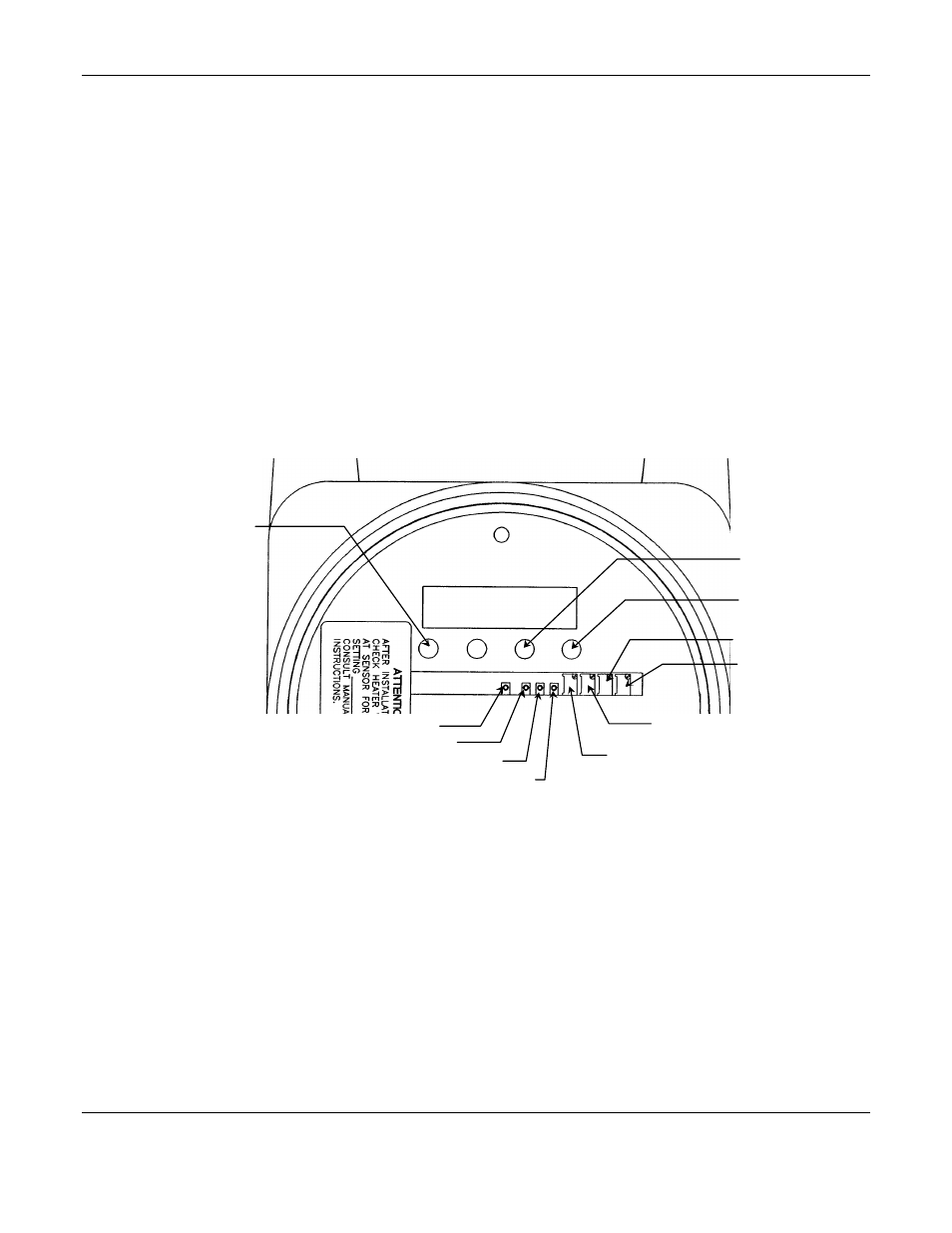
Figure 8: Control Unit Oxygen Channel
PROCEDURE:
1. Set the Purge/Operate/Horn-off switch to HORN-OFF. Open the oxygen cell housing. Remove the cell from the
circuit board (do not touch the screen on the cell).
2. Connect the negative voltmeter lead to TP101 and the positive voltmeter lead to TP102 (on the oxygen channel
circuit board in the display plate).
3. Adjust the null adjust potentiometer R108 (on oxygen channel circuit board) so the voltmeter shows 0.00 V
DC
between test points TP101 and TP102.
4. LOW LEVEL SET ADJUST:
a) Reconnect the oxygen cell.
b) To check oxygen cell output, measure the voltage between the cell lead. This should be between 0.043 V
DC
and
0.09 V
DC
.
c) Connect the negative lead of the voltmeter to TP101 and the positive lead to TP103 in the main circuit board of
the monitor.
d) Adjust the low level set potentiometer, R112, to give .766 V
DC
between TP101 and TP103.
O
XYGEN
M
ETER
Alarm LED
Red
Power LED
Green
Horn Off LED
Red
R108
R110
R112
R116
TP101
TP102
TP103
TP101