ENMET ISA-44-RALE-OD User Manual
Page 11
ISA-44RALE-OD/ISA-44RAHE-OD/ISA-44E-OD
ENMET Corporation
7
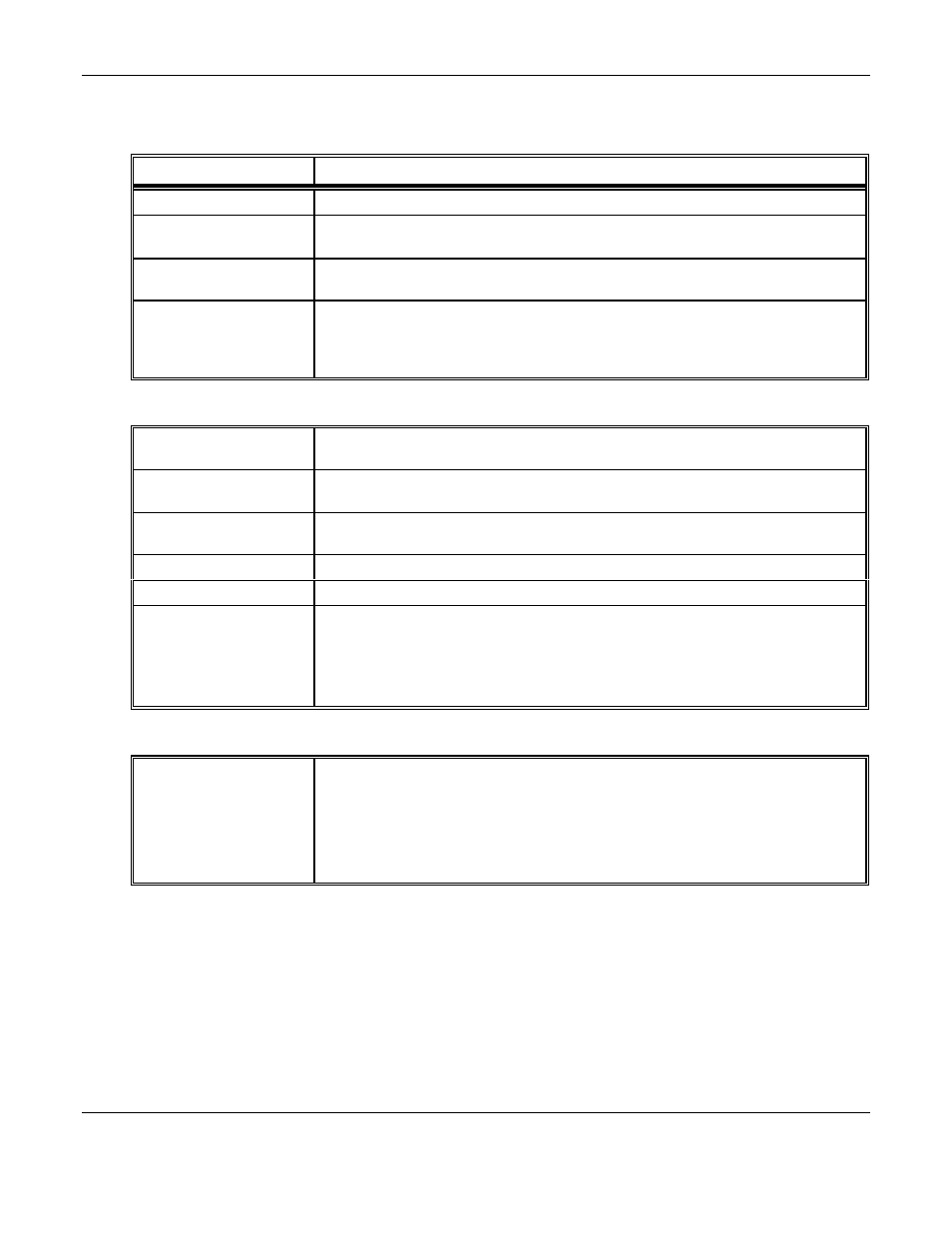
Oxygen Channel:
Feature
Description
Meter
Indicates percent by volume oxygen in sampled air. Linear scale.
Power LED
This green LED indicates that the oxygen channel is in non-alarm, operating condition.
This gives positive indication that the channel is operating.
Alarm LED
This red LED indicates that the oxygen content of respiratory air contains less than
19.5% oxygen by volume. See section 4.3 Oxygen Alarm State.
Horn-Off LED
This orange LED is not actually part of the oxygen channel, although it is located next
to the oxygen channel LED's. It is activated when the Purge/Operate/Horn-off switch is
set to the "Horn-Off" position, indicating that the factory installed horn is disengaged
and thus will not activate during oxygen or gas alarms.
Gas Monitoring Channel:
Meter
Indicates level of gas. This meter is not a linear device. Do not infer exact readings
from unmarked points on the scale.
Fault LED
This red LED indicates sensor fault for the gas channel. See description of sensor fault
condition in section 4.3 Sensor Fault Alarm State.
Power LED
This green LED indicates a non-alarm operating condition for the gas channel. This
provides positive indication that the channel is operating.
Low Alarm LED
This amber LED indicates low alarm condition for the gas channel.
High Alarm LED
This red LED indicates high alarm condition for the gas channel.
Purge LED
This orange LED indicates that the Purge/Operate/Horn-off Switch has been set to
PURGE, which increases the sensor heater voltage to clear off contaminants from the
surface of the MOS sensor.
NOTE: During purging, the MOS sensor does not monitor the gas content of the
sampled air.
All Channels: See figure 1
Potentiometers /
Test Points
These are small components located directly on the circuit board of each channel. A
small screw in each potentiometer adjusts circuit voltages to affect the response of the
instrument.
The test points are used together with a voltmeter to check the potentiometer voltage
adjustments.
Do not adjust the potentiometers except during calibration procedures (see section 6.0).