ENMET ISA-200-RAL (O) User Manual
Page 11
ISA 200 RAL (O)
ENMET Corporation
7
In addition, there is a fault relay, which changes state whenever the instrument is in a fault condition.
The contact positions are given in Table 2:
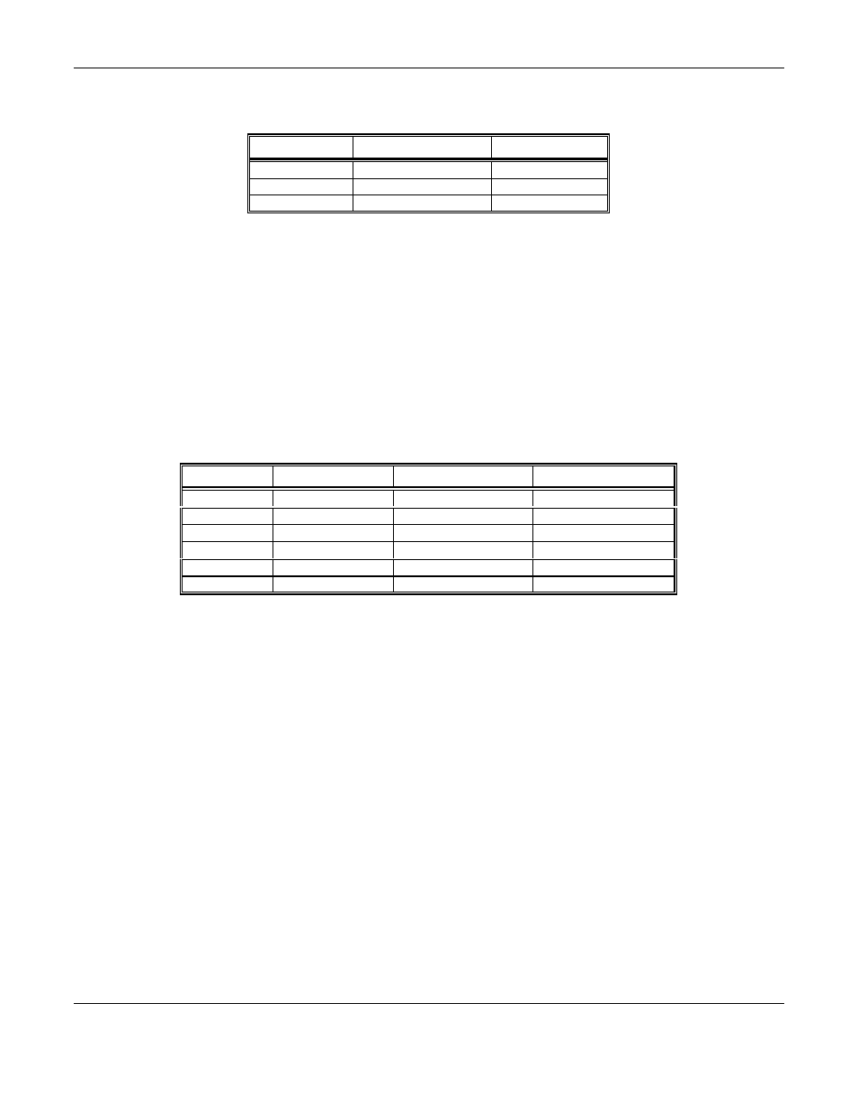
Table 2: Fault Relay Contacts
Position
Function
Contact
13
Fault
NC
14
Fault
C
15
Fault
NO
The coil of this relay is energized when the instrument is in the non-fault state; the contact conditions given above are
for the non-energized state, which is identical to the fault state.
These relay contacts can be used to operate auxiliary alarms or other functions. Punch a hole at the bottom of the left
side of the enclosure for a wire exit, and use appropriate cable and fittings to preserve the NEMA-12 rating of the
enclosure.
3.4.2 Optional 4-20mA Outputs
Isolated 4-20 mA outputs are available for data logging or other purposes. An output is supplied for each sensor
supplied in a particular instrument, and can be added when a sensor is added in the field. When all three sensors are
supplied, these outputs are available on the terminal strip in the positions given in Table 3:
Table 3: Outputs for 4-20mA
Position
Channel
Function
Range
16
CO
Ground
4 mA = 0 ppm
17
CO
+ 4 to 20 mA
20 mA = 100 ppm
18
Not Used
19
Not Used
20
O2
Ground
4 mA = 0%
21
O2
+ 4 to 20 mA
20 mA = 25.5%
When both sensors are supplied, the sensor for CO output is on positions 16 and 17. The Oxygen output is on
positions 20 and 21. Positions 18 & 19 are not used.
Wiring requirements are the same as for the relays.
3.5 Initial Calibration
If a calibration kit is available, calibrate the CO and O
2
channels of the instrument 24 hours after installation. See
Section 5.0, Maintenance, for calibration instructions. After calibration, be sure to return the red sample-calibrate
valve handle to the down position, pointing toward the sample input port.