Signal flow, Function switches – EMM Labs DAC8 MKIV User Manual
Page 3
2
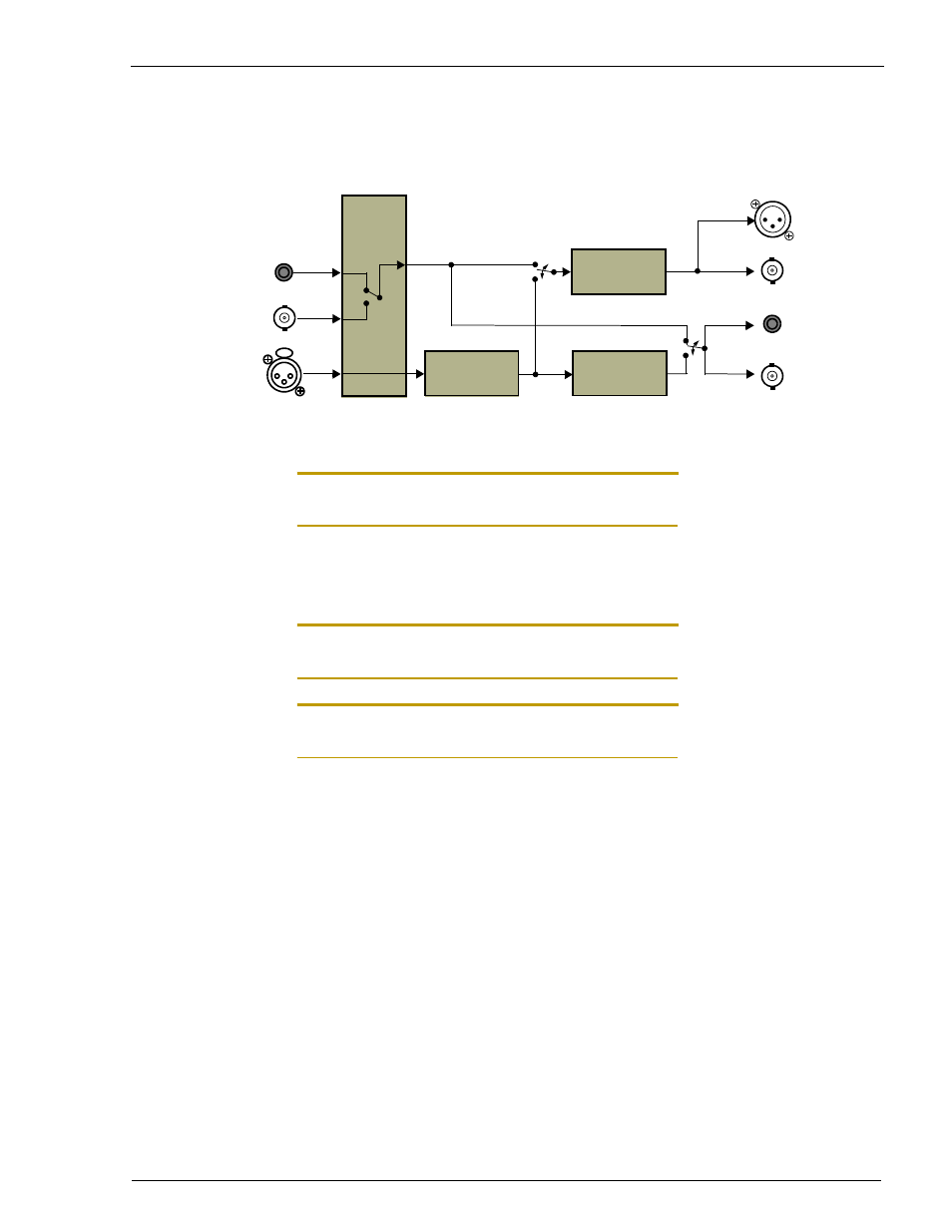
Signal flow
Note: Analog inputs are balanced with pin 2 hot, pin 3 cold and pin 1 GND. For unbalanced
inputs just connect to pin 2 and tie pin 3 to GND.
Function Switches
Note: Some configurations require long settling times of up to several seconds after changing
switch positions.
Note: The powerup sequence and initial calibration of the unit takes about 20 seconds after
power is applied.
Clock Section
INT /EXT:
Selects internal or external clock source. LOCK LED is lit
when A/D converter is locked to external clock.
OPTIC / BNC:
Selects external clock between optical and BNC formats.
Sample Rate Section
64 / 128:
Selects oversampling ratio. 128 position does not allow
2FS PCM generation (error light on).
1FS / 2FS:
Selects the sample rate for PCM data. FS is the base
frequency (see 44.1 / 48 switch). 2FS position will mute
outputs when the oversampling ratio is set to 128.
44.1 / 48:
Selects the base frequency (only 44.1kHz is allowed for
DSD outputs and inputs).
A/D
Conversion
DC Removal
DSD
DSD
DSD
PCM
PCM
DSD (Optical)
Analog
DSD (RAW/SDIF3)
(shared Conn.)
(shared Conn.)
DSD to PCM
Conversion
(AES/EBU)
(SDIF2)
(optical)
DSD