Assemble components to the pc board – Elenco Logic Pulser Kit User Manual
Page 7
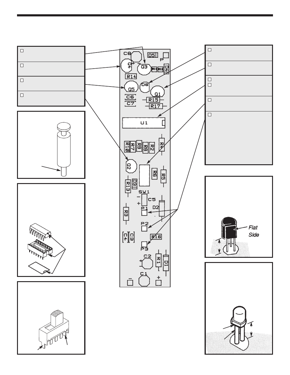
ASSEMBLE COMPONENTS TO THE PC BOARD
Refer to the top legend on the PC board, install and solder the following components.
Install and solder the IC
socket. Insert the IC into the
socket with the notch in the
direction shown on the top
legend.
Figure 5
Mount the transistor with the
flat side in the direction shown
on the top legend. Leave 1/4”
between the part and PC
board.
Figure 7
Cut a 3/8” piece of tubing for
each LED lead, to be used as
stand-offs.
Mount the LED
with the flat side in the
direction shown on the top
legend.
Figure 8
Insert the tabs and terminals
into the PC board.
Solder
terminals only.
Figure 6
-6-
Flat
Tubing
3/8”
Q3 - 2N3906 Transistor
(see Figure 7)
Q4 - 2N3904 Transistor
(see Figure 7)
Q5 - 2N3904 Transistor
(see Figure 7)
Q2 - 2N3906 Transistor
(see Figure 7)
D6 - LED
(see Figure 8)
Q1 - 2N3904 Transistor
(see Figure 7)
U1 - 14-Pin IC Socket
U1 - 74C04 IC or 4069
(see Figure 5)
SW1 - Switch
(see Figure 6)
P1, P2, P3 - Pins
Do not install the pins to the
PC board.
They will be
installed later. Tin (that is, put
a small amount of solder on)
the foil around the holes for
the three pins.
Do not block
the hole. Tin the bottom fo
the pin as shown in Figure 4.
Notch
Figure 4
Tab
Tab
1/4”
Tin Here