Identifying resistor values, Introduction, Circuit description identifying capacitor values – Elenco Logic Pulser Kit User Manual
Page 3
-2-
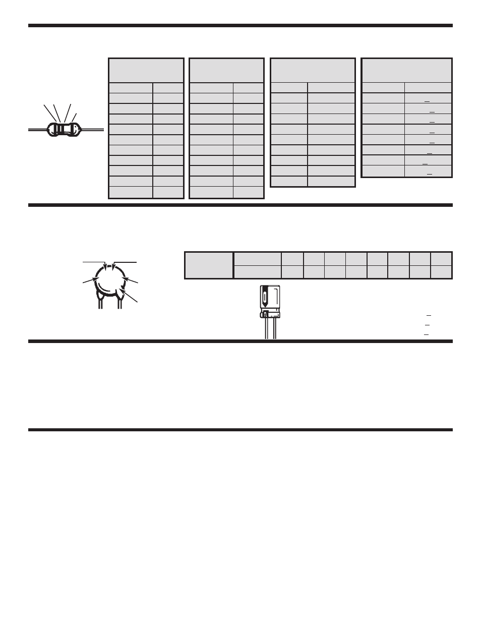
IDENTIFYING RESISTOR VALUES
Use the following information as a guide in properly identifying the value of resistors.
BAND 1
1st Digit
Color
Digit
Black
0
Brown
1
Red
2
Orange
3
Yellow
4
Green
5
Blue
6
Violet
7
Gray
8
White
9
BAND 2
2nd Digit
Color
Digit
Black
0
Brown
1
Red
2
Orange
3
Yellow
4
Green
5
Blue
6
Violet
7
Gray
8
White
9
Multiplier
Color
Multiplier
Black
1
Brown
10
Red
100
Orange
1,000
Yellow
10,000
Green
100,000
Blue
1,000,000
Silver
0.01
Gold
0.1
Resistance
Tolerance
Color
Tolerance
Silver
+10%
Gold
+5%
Brown
+1%
Red
+2%
Orange
+3%
Green
+.5%
Blue
+.25%
Violet
+.1%
Bands
1
2
Multiplier
Tolerance
INTRODUCTION
Assembly of your LP-425 Logic Pulser will prove to
be an exciting project and give much satisfaction
and personal achievement. If you have experience
in soldering and wiring technique, you should have
no problems. For the beginner, care must be given
in identifying the proper components and in good
soldering habits.
Above all, take your time and
follow the easy step-by-step instructions.
Remember, “an ounce of prevention is worth a
pound of cure”.
Avoid making mistakes and no
problems will occur.
The Elenco Model LP-425 Logic Pulser is a very
handy device for inspecting and repairing logic
circuits. By injecting a signal directly to the circuit,
you can avoid removing the ICs or other circuit
components. The Logic Pulser will thus help you to
troubleshoot wiring errors and malfunctioning
components.
The Logic Pulser operates by
producing a large transient current for a short period
of time. This will not harm the components under
test since the average current is very small. The
injected voltage is produced by the transient current
flowing through the inherent resistance of the circuit.
The LP-425 Logic Pulser can produce a 10
microsecond pulse at 100mA load.
The signal
frequency can be set to .5Hz or 400Hz by the pulse
repetition rate switch on the front of the Logic
Pulser. This feature makes the Logic Pulser a very
effective tool. The Logic Pulser also has a square
wave output terminal (SQ).
When the pulse
repetition rate switch is set to 400Hz, the signal on
the square wave terminal is a square wave. When
the switch is set to .5Hz, the signal on the terminal
is a pulse, high for 90% of the time and ground for
the remaining 10%. The sync input terminal (SYNC)
Logic Pulser can be used to produce an externally
synchonized signal at the output.
CIRCUIT DESCRIPTION
IDENTIFYING CAPACITOR VALUES
Second Digit
First Digit
Multiplier
Tolerance
*
For the No.
0
1
2
3
4
5
8
9
Multiply By
1
10
100
1k
10k 100k
.01
0.1
Multiplier
Note: The letter “R” may be used at times to
signify a decimal point; as in 3R3 = 3.3
10
m
F 16V
103K
100V
The letter M indicates a tolerance of +20%
The letter K indicates a tolerance of +10%
The letter J indicates a tolerance of +5%
Maximum Working Voltage
The value is 10 x 1,000 = 10,000pF or .01
m
F 100V
*
Capacitors will be identified by their capacitance value in
pF (picofarads), nF (nanofarads), or
m
F (microfarads).
Most capacitors will have their actual value printed on
them. Some capacitors may have their value printed in
the following manner. The maximum operating voltage
may also be printed on the capacitor.