Sw2 mfd position – Elenco Capacitor Substitution Box User Manual
Page 7
-6-
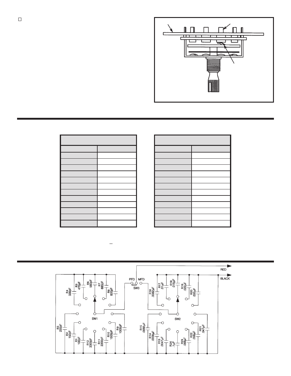
Installation of Knobs without Capacitance Meter
If a capacitance meter is not available, turn both
switches so that the wiper contact is in the position
shown in Figure 5. Start with switch SW1, follow the
copper run on the PC board from the lug in contact
with the wiper to the 680pF (R7) capacitor, to be
sure that the switch is set in the proper position.
Align the knob on the SW1 (PFD) switch to the
680pF position, push the knob onto the shaft.
Follow the same procedure for switch SW2 (MFD),
except follow the copper run to the .0047
m
F (R13)
capacitor. Align the knob on the SW2 (MFD) switch
to the .0047
m
F position.
TESTING THE CIRCUIT
SCHEMATIC DIAGRAM
SW1 PFD POSITION
Value Position
Meter Reading
100pF
150pF
220pF
330pF
470pF
560pF
680pF
820pF
1000pF
1500pF
2200pF
3300pF
SW2 MFD POSITION
Value Position
Meter Reading
.0047
m
F
.0056
m
F
.0068
m
F
.0082
m
F
.01
m
F
.015
m
F
.022
m
F
.033
m
F
.047
m
F
.056
m
F
.068
m
F
.1
m
F
Note: Capacitors being tested have a 10% tolerance. Because of lead capacitance from the alligator clips to
the PC board, all values will read 30pF +10pF above the actual capacitance value.
Figure 5
Wiper Contact
Lug
PC Board