Project #550, Solar control, Project #551 – Elenco Upgrade Kit SC500 to SC750 User Manual
Page 26: Solar resistance meter, Solar diode tester, Project #552
-25-
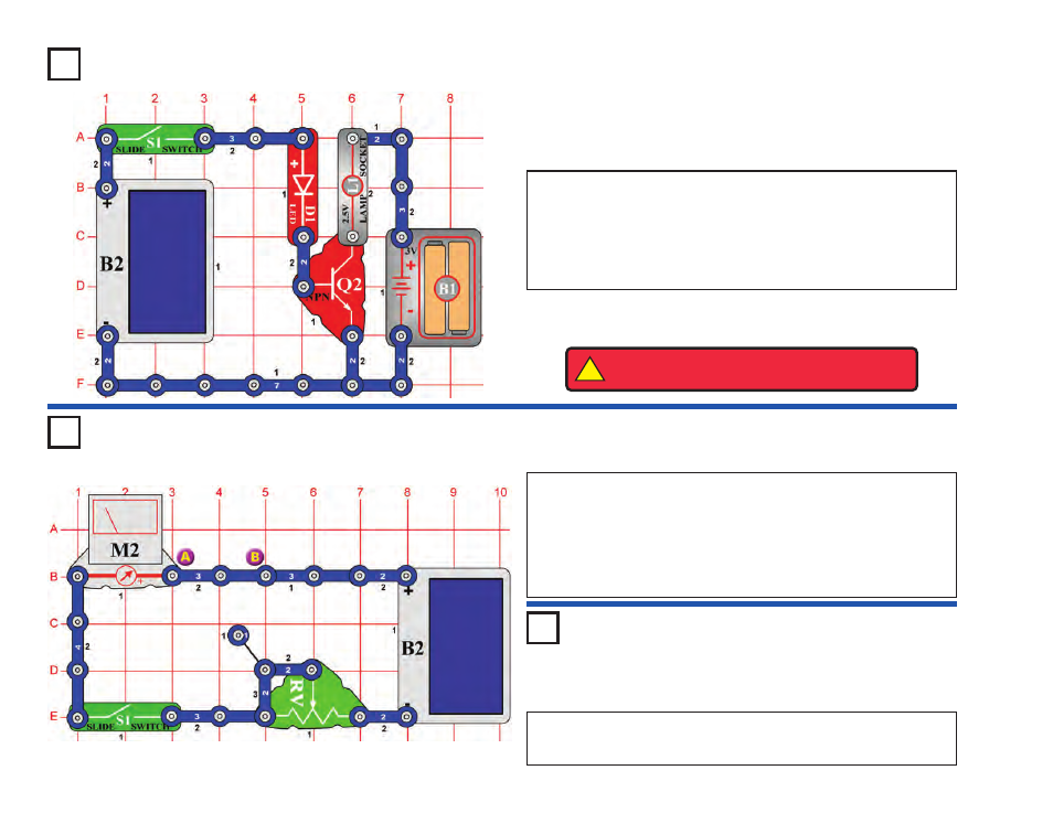
Build the circuit and turn on the slide switch (S1). If there is sunlight
on the solar cell (B2), then the LED (D1) and lamp (L1) will be on.
This circuit uses the solar cell to light the LED and to control the lamp.
The solar cell does not produce enough power to run the lamp directly.
You can replace the lamp with the motor (M1, “+” side on top) and fan;
the motor will spin if there is sunlight on the solar cell.
Project #550
OBJECTIVE: To learn about solar power.
Solar Control
Place the circuit near a bright light and set the adjustable resistor (RV) so that
the meter (M2) reads “10” on the LOW (or 10mA) setting. Now replace the 3-
snap between points A & B with another component to test, such as a resistor,
capacitor, motor, photoresistor, or lamp. The 100
μ
F (C4) or 470
μ
F (C5)
capacitors will give a high reading that slowly drops to zero.
You can also use the two-spring socket (?1) and place your own components
between its springs to test them.
Project #551
OBJECTIVE: To test the resistance of your components.
Solar Resistance Meter
OBJECTIVE: To learn about solar power.
Solar Diode Tester
Use the same circuit to test the red and green LED’s (D1 & D2), and the diode
(D3). The diode will give a higher meter reading than the LED’s, and all three
will block current in one direction.
Project #552
!
WARNING:
Moving parts. Do not touch the fan or
motor during operation. Do not lean over the motor.