Project b11 adjustable blinker – Elenco Snap Circuits XP ® User Manual
Page 45
Project B11
Adjustable Blinker
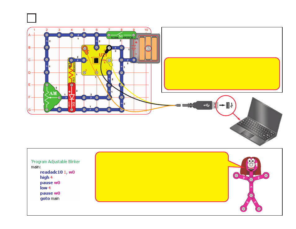
Build the circuit as shown. Turn on the slide switch (S1). Load
program Adjustable Blinker into the microcontroller (U21) using
the programming instructions in project B1. The red LED (D1)
will be blinking. Adjust the lever on the adjustable resistor (RV)
to adjust the blink rate.
Optional:
-44-
At some RV settings, the red LED may be blinking so fast that it
appears to stay on continuously. The reason is that your eyes cannot
adjust fast enough. They continue to see what they have just seen.
This concept is used in movie theaters, where film frames are flashed
on the screen at a fast rate. Your eyes see this fast series of flashes
as a continuous movie.
This program tells the microcontroller to measure the voltage at input pin 1,
then use that value to adjust the delay in turning output 4 on and off. The red
LED is connected to output 4, so it will blink. The adjustable resistor sets the
voltage to input 1.
The
Readadc10
command configures pin 1 to be an analog-to-digital converter
(ADC) input, and measures the voltage there. The voltage (analog, an electrical
signal) is converted to digital (a number), so it can be stored in the
microcontroller’s memory. The measured number will be from 0 to 1023, due to
10-bit measurement accuracy. More details on how this command works can
be found under the Help menu at Snap Circuits
®
XP
TM
.